
In the realm of modern manufacturing, the evolution toward CNC (Computer Numerical Control) technology represents a frontier of immense significance, particularly in the complex domain of gear production. As a researcher deeply involved in mechanical engineering and gear transmission systems, I have dedicated considerable effort to understanding and advancing the methodologies behind gear milling, especially for spiral bevel and hypoid gears. These gears are pivotal in applications requiring high torque transmission between intersecting or non-intersecting shafts, such as in automotive differentials, aerospace systems, and industrial machinery. The transition from mechanical gear milling machines to CNC-based systems marks a revolutionary leap, offering enhanced precision, flexibility, and efficiency. This paper, from my first-person perspective, delves into the intricate principles of gear milling on CNC machines, focusing on the mathematical foundations that enable the generation of accurate gear tooth surfaces. I will explore the coordinate transformations, surface equations, and computational techniques that underpin this advanced gear milling process, emphasizing the keyword “gear milling” throughout to highlight its centrality in modern manufacturing.
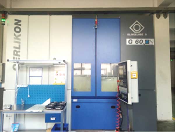
The advent of CNC gear milling machines has fundamentally transformed the landscape of gear manufacturing. Traditional mechanical machines, with their complex arrangements of cams, gears, and linkages, are increasingly being phased out in favor of CNC systems that offer superior control and adaptability. In my research, I have focused on a six-axis CNC gear milling machine capable of producing both spiral bevel and hypoid gears. This machine eliminates the need for mechanical components like the cradle, eccentric mechanisms, and tool tilt adjustments, thereby simplifying the structure while enhancing performance. The six axes of motion include: linear movements of the cutter head in the horizontal (X) and vertical (Y) directions, rotational motion of the workpiece (A), rotational motion of the cutter head (C), linear movement of the workpiece along its axis (Z), and the conical angle adjustment of the workpiece (B). When employing a method without tool tilt, B remains constant, and the cutter head traces an arc in the XY plane, mimicking the motion of a traditional generating gear milling process. This CNC approach not only streamlines the gear milling operation but also opens up possibilities for innovative machining strategies, such as using a translating conical surface to form a generating rack for cylindrical gears—a concept I will elaborate on later.
To fully appreciate the capabilities of CNC gear milling, it is essential to understand the underlying kinematic and geometric principles. In traditional gear milling, a hypothetical generating gear, often a crown gear or a planar rack, is used to envelope the tooth surface of the workpiece through relative motion. In the CNC context, these motions are digitally controlled, allowing for precise replication and even enhancement of these generating processes. For instance, in milling spiral bevel gears, the cutter head rotates while following a circular path in the XY plane around a virtual cradle center, thereby forming the generating surface of a crown gear. However, my investigations have led me to propose a more versatile approach: by translating the cutter head linearly while it rotates, we can effectively create a generating rack with a conical surface. This method is particularly advantageous for producing cylindrical gears with straight or helical teeth, extending the utility of the CNC gear milling machine beyond bevel gears. The mathematical modeling of this process begins with defining coordinate systems and deriving the equations of motion.
In gear milling, the generation of tooth surfaces is fundamentally a problem of enveloping theory. To derive the necessary equations, I establish several coordinate systems. Let \( O_P, x_P, y_P, z_P \) be the coordinate system fixed to the generating rack (or generating gear), and \( O_H, x_H, y_H, z_H \) be the system attached to the cutter head. The cutter head, typically a face-mill cutter with multiple blades, rotates about its axis. For a conical generating surface, the position vector of a point on this surface can be expressed in terms of parameters \( u \) and \( \theta \), which represent the radial distance and angular position, respectively. The cutter head’s installation relative to the generating rack is defined by parameters such as the cutter radius \( r_H \) and orientation angles. The equation of the generating surface in the rack coordinate system is given by:
$$ x_P = r_H \tan \alpha – u \cos \alpha, $$
$$ y_P = u \sin \alpha \sin(\theta – q) – b_H \sin q, $$
$$ z_P = u \sin \alpha \cos(\theta – q) + b_H \cos q, $$
where \( \alpha \) is the cone angle of the generating surface, \( q \) is an angular offset, and \( b_H \) is a linear offset. This parametric representation captures the geometry of the conical surface used in gear milling. The next step involves defining the relative motion between this generating surface and the workpiece. For cylindrical gear generation, the generating rack translates linearly, while the workpiece rotates. The meshing condition, which ensures continuous contact between the generating surface and the gear tooth surface, is derived from the requirement that the relative velocity at the contact point is orthogonal to the common normal vector. This leads to the meshing equation:
$$ n_{x_P} (v_{y_P} + r \dot{\phi}) – n_{y_P} v_{x_P} = 0, $$
where \( \mathbf{n} = (n_{x_P}, n_{y_P}, n_{z_P}) \) is the unit normal vector of the generating surface, \( v_{x_P} \) and \( v_{y_P} \) are components of the relative velocity, \( r \) is the reference radius of the gear, and \( \dot{\phi} \) is the angular velocity of the workpiece. Substituting the expressions for the generating surface into this equation yields a relation between \( u \), \( \theta \), and the workpiece rotation angle \( \phi \). For each value of \( u \), we can solve for \( \phi \), thereby determining a line of contact on the generating surface. Transforming these contact lines into the coordinate system fixed to the workpiece \( S_1 \) gives the corresponding lines on the gear tooth surface. The gear tooth surface is the envelope of all such contact lines over one complete cycle of motion. The transformation equations are:
$$ x_1 = x_P \cos \phi + y_P \sin \phi + r \cos \phi + r \phi \sin \phi, $$
$$ y_1 = -x_P \sin \phi + y_P \cos \phi – r \sin \phi + r \phi \cos \phi, $$
$$ z_1 = z_P. $$
This formulation allows for the precise calculation of tooth profiles in gear milling. It is important to note that the resulting tooth surface for cylindrical gears may not be a true helical surface unless specific motion laws are applied; however, by using separate inner and outer cutter blades, conjugate tooth flanks can be generated for paired gears, enabling controlled contact patterns through adjustments in cutter radius. This flexibility is a key advantage of CNC gear milling, as it permits optimization of gear meshing performance.
Beyond cylindrical gears, the CNC gear milling machine excels in producing spiral bevel and hypoid gears, which are essential for power transmission between non-parallel shafts. Hypoid gears, in particular, involve offset axes and complex geometry, making their manufacture one of the most challenging aspects of gear milling. The mathematical modeling of hypoid gear generation requires a detailed analysis of the pitch cones. Consider two pitch cones representing the gear and pinion, with their axes arranged as skew lines in space. Let the coordinate systems for the pinion (1) and gear (2) be defined relative to a fixed global system. The parametric equations for the cone surfaces are:
For cone 1 (pinion):
$$ x_1^{(1)} = r_1 \cos \theta_1, \quad y_1^{(1)} = r_1 \sin \theta_1, \quad z_1^{(1)} = r_1 \tan \gamma_1, $$
For cone 2 (gear):
$$ x_2^{(2)} = r_2 \cos \theta_2, \quad y_2^{(2)} = r_2 \sin \theta_2, \quad z_2^{(2)} = -r_2 \tan \gamma_2, $$
where \( r_1, r_2 \) are radial distances, \( \theta_1, \theta_2 \) are angular parameters, and \( \gamma_1, \gamma_2 \) are cone angles. Transforming these into a common coordinate system \( S_0 \) with origin at the intersection of the axes offsets yields:
$$ x_1^{(0)} = x_1^{(1)} + E, \quad y_1^{(0)} = y_1^{(1)} – e_1, \quad z_1^{(0)} = z_1^{(1)}, $$
$$ x_2^{(0)} = x_2^{(2)}, \quad y_2^{(0)} = y_2^{(2)}, \quad z_2^{(0)} = z_2^{(2)} – e_2, $$
with \( E \) as the offset distance and \( e_1, e_2 \) as axial shifts. At the point of contact, the coordinates must match, and the normal vectors must be collinear. This leads to a system of equations that determine the conjugate surfaces. The conditions for contact are:
$$ x_1^{(0)} = x_2^{(0)}, \quad y_1^{(0)} = y_2^{(0)}, \quad z_1^{(0)} = z_2^{(0)}, $$
and
$$ \mathbf{n}_1^{(0)} \parallel \mathbf{n}_2^{(0)}, $$
where the normal vectors are derived from the cone geometry. Expanding these conditions gives equations such as:
$$ r_1 \cos \theta_1 + E = r_2 \cos \theta_2, $$
$$ r_1 \tan \gamma_1 = r_2 \sin \theta_2, $$
$$ r_1 \sin \theta_1 = -r_2 \tan \gamma_2 – e_2. $$
Additionally, the direction vectors of the cone generators at the contact point must satisfy the spiral angle relationship. The spiral angles \( \psi_1 \) and \( \psi_2 \) for the pinion and gear, respectively, are related by:
$$ \psi_1 = \psi_2 + \sigma, $$
where \( \sigma \) is the shaft angle. The tangent vectors at the contact point are:
$$ \mathbf{t}_1^{(0)} = (\sin \gamma_1 \cos \theta_1, \cos \gamma_1, \sin \gamma_1 \sin \theta_1), $$
$$ \mathbf{t}_2^{(0)} = (\sin \gamma_2 \cos \theta_2, \sin \gamma_2 \sin \theta_2, -\cos \gamma_2), $$
and their dot product gives the angle between them. The meshing of hypoid gears in gear milling also requires consideration of curvature matching to ensure proper contact patterns. The principal curvatures at the contact point must be compatible with the cutter geometry. For a face-mill cutter used in gear milling, the effective radius \( r_c \) is related to the gear parameters by:
$$ r_c = \frac{\tan \psi_1 – \tan \psi_2}{\pm \tan \phi_0 \left( \frac{\tan \psi_1}{L_1 \tan \gamma_1} + \frac{\tan \psi_2}{L_2 \tan \gamma_2} \right) + \left( \frac{1}{L_1 \cos \psi_1} – \frac{1}{L_2 \cos \psi_2} \right) }, $$
where \( \phi_0 \) is the limiting pressure angle, and \( L_1, L_2 \) are the cone distances. This equation ensures that the cutter profile matches the desired tooth curvature, a critical aspect of hypoid gear milling. To solve for the gear design parameters, we typically start with given initial values for \( r_1 \) and \( r_2 \), then iterate using the above equations to satisfy all geometric and kinematic constraints. This iterative process is well-suited to CNC gear milling, where digital controllers can adjust motions in real-time to achieve optimal results.
To summarize the key parameters and equations involved in CNC gear milling for spiral bevel and hypoid gears, I present the following tables and formulas. These summaries are intended to provide a quick reference for practitioners and researchers in the field of gear milling.
| Parameter | Symbol | Description |
|---|---|---|
| Cutter Radius | \( r_H \) | Radius of the face-mill cutter used in gear milling. |
| Cone Angle | \( \alpha \) | Angle of the generating conical surface. |
| Spiral Angle | \( \psi \) | Helix angle of the gear tooth, crucial for smooth engagement. |
| Offset Distance | \( E \) | Axis offset in hypoid gear milling. |
| Cone Distance | \( L \) | Distance from apex to point on pitch cone. |
| Pressure Angle | \( \phi_0 \) | Angle defining tooth profile in gear milling. |
Table 1 lists fundamental parameters that must be carefully selected during the gear milling process. Each parameter influences the tooth geometry and meshing performance, underscoring the importance of precise calculation in CNC gear milling.
| Coordinate System | Notation | Purpose |
|---|---|---|
| Generating Rack System | \( S_P (O_P, x_P, y_P, z_P) \) | Fixed to the hypothetical generating rack. |
| Cutter Head System | \( S_H (O_H, x_H, y_H, z_H) \) | Fixed to the rotating cutter in gear milling. |
| Workpiece System | \( S_1 (O_1, x_1, y_1, z_1) \) | Fixed to the gear being milled. |
| Global Reference System | \( S_0 (O_0, x_0, y_0, z_0) \) | Stationary frame for overall motion analysis. |
Coordinate systems are essential for deriving the equations of motion in gear milling. Transformations between these systems enable the calculation of tooth surfaces as envelopes of the generating surface.
The mathematical derivations in gear milling can be further condensed into core formulas. The generating surface equation for a conical rack is central:
$$ \mathbf{r}_P(u, \theta) = \begin{pmatrix} r_H \tan \alpha – u \cos \alpha \\ u \sin \alpha \sin(\theta – q) – b_H \sin q \\ u \sin \alpha \cos(\theta – q) + b_H \cos q \end{pmatrix}. $$
The meshing condition for cylindrical gear generation is:
$$ \sin \alpha [u \sin \alpha \sin(\theta – q) – b_H \sin q + r \dot{\phi}] – \cos \alpha \sin(\theta – q)(r_H \tan \alpha – u \cos \alpha) = 0. $$
For hypoid gears, the contact conditions include:
$$ r_1 \cos \theta_1 + E = r_2 \cos \theta_2, $$
$$ r_1 \tan \gamma_1 = r_2 \sin \theta_2, $$
$$ r_1 \sin \theta_1 = -r_2 \tan \gamma_2 – e_2, $$
and the normal vector parallelism condition reduces to:
$$ -\sin \gamma_1 \sin \gamma_2 = \cos \gamma_2 \cos \gamma_1 \sin \theta_1 \sin \theta_2, $$
$$ \cos \gamma_1 \cos \gamma_2 \cos \theta_1 \sin \theta_2 = -\sin \gamma_1 \cos \gamma_2 \cos \theta_2. $$
These equations form the backbone of the computational algorithms used in CNC gear milling machines. By solving them numerically, we can determine the tool paths and machine settings required to produce accurate gears. The iterative nature of these calculations highlights the synergy between advanced mathematics and modern manufacturing in gear milling.
In practice, the gear milling process on a CNC machine involves several steps. First, the gear design parameters are input into a computer-aided manufacturing (CAM) software. This software uses the equations discussed above to generate the NC (Numerical Control) code that drives the six axes of the machine. During gear milling, the cutter head rotates at high speed while the workpiece moves according to the programmed trajectories. The linear and rotational motions are synchronized to ensure that the generating surface envelopes the tooth space. For spiral bevel gears, the cutter head typically follows an arcuate path, whereas for hypoid gears, additional offset motions are incorporated. The ability to adjust parameters like cutter radius and orientation in real-time allows for fine-tuning of the tooth contact pattern, which is critical for noise reduction and load distribution. This adaptability is a hallmark of CNC gear milling, setting it apart from conventional methods.
Moreover, the CNC gear milling machine can be employed for both generating and forming processes. In generating gear milling, the relative motion between cutter and workpiece simulates the meshing of a pair of gears, resulting in conjugate tooth surfaces. In forming gear milling, the cutter shape directly corresponds to the tooth space, and the workpiece is indexed after each cut. The CNC approach seamlessly integrates both methods, enabling efficient production of gears with various specifications. For instance, in mass production of automotive differential gears, CNC gear milling offers rapid cycle times and consistent quality. The keyword “gear milling” encompasses all these variations, underscoring its broad applicability in industry.
To illustrate the computational flow in hypoid gear milling, I outline a typical procedure:
- Specify initial parameters: gear tooth numbers \( N_1, N_2 \), shaft angle \( \sigma \), offset \( E \), and spiral angles \( \psi_1, \psi_2 \).
- Calculate pitch cone angles \( \gamma_1, \gamma_2 \) using geometric relations.
- Determine cone distances \( L_1, L_2 \) based on gear blank dimensions.
- Solve the contact equations iteratively to find \( r_1, r_2, \theta_1, \theta_2, e_1, e_2 \).
- Compute cutter radius \( r_c \) from curvature matching conditions.
- Generate NC code for the six-axis motions, incorporating tool paths derived from the generating surface equations.
- Simulate the gear milling process to verify tooth geometry and contact pattern.
- Perform actual machining on the CNC gear milling machine.
This procedure emphasizes the integral role of mathematical modeling in every stage of gear milling. The equations ensure that the manufactured gears meet design specifications for strength, efficiency, and durability.
In conclusion, CNC gear milling represents a paradigm shift in the manufacture of spiral bevel and hypoid gears. Through first-principles analysis and advanced mathematical modeling, we can harness the full potential of six-axis CNC machines to produce gears with unprecedented precision and performance. The derivations presented in this paper—from generating surface equations to hypoid contact conditions—provide a comprehensive framework for understanding and implementing gear milling processes. As a researcher, I believe that continued innovation in this field will drive further advancements in gear technology, with applications spanning automotive, aerospace, and robotics. The keyword “gear milling” encapsulates not just a manufacturing technique but a multidisciplinary endeavor that blends mechanics, mathematics, and digital control. By embracing these complexities, we can unlock new possibilities in power transmission and mechanical design.