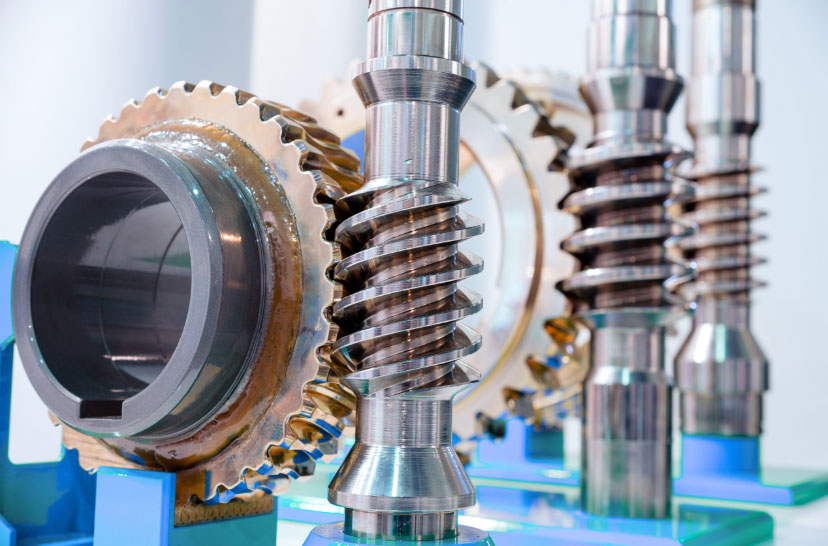
Worm gear reducers are critical components in low-speed, high-torque industrial applications. Their unique design, featuring a worm (screw-like gear) meshing with a worm wheel (helical gear), enables compact power transmission with high reduction ratios. However, operational challenges such as wear, vibration, and thermal stress necessitate systematic maintenance. This article analyzes failure mechanisms, provides mitigation strategies, and introduces advanced material solutions for enhanced durability.

1. Structural Characteristics of Worm Gear Systems
The RV-series worm gear reducer exemplifies modern design with these key components:
| Component | Material | Function |
|---|---|---|
| Worm | 20CrMnTi (Carburized) | Power input through helical threads |
| Worm Wheel | ZCuSn10P1 (Tin Bronze) | Power output via conjugate meshing |
| Housing | ZL401 Aluminum Alloy | Heat dissipation & structural support |
| Bearings | GCr15 Bearing Steel | Radial/axial load management |
The meshing efficiency of worm gears is expressed as:
$$
\eta = \frac{\tan \gamma}{\tan (\gamma + \rho)}
$$
Where:
$\gamma$ = Lead angle of worm
$\rho$ = Friction angle
2. Failure Modes and Corrective Actions
2.1 Thermal Overload
| Root Cause | Diagnostic Method | Remediation |
|---|---|---|
| Excessive loading (>120% rated torque) | Infrared thermography | Implement torque limiter |
| Lubricant degradation (viscosity <68 cSt @40°C) | Oil analysis spectroscopy | Replace with ISO VG 320 EP oil |
| Misalignment (>0.05mm/mm) | Laser alignment check | Realign within 0.02mm/mm tolerance |
2.2 Lubrication Failure
The minimum required lubricant film thickness is calculated by:
$$
h_{min} = 2.65 \frac{(U^{0.7} \cdot G^{0.6} \cdot W^{-0.13})}{E^{0.03}}
$$
Where:
$U$ = Speed parameter
$G$ = Material parameter
$W$ = Load parameter
$E$ = Equivalent elastic modulus
3. Advanced Material Solutions
Comparative analysis of worm wheel materials:
| Material | Wear Rate (mm³/Nm) | Max PV Value (MPa·m/s) | Cost Index |
|---|---|---|---|
| ZCuSn10P1 | 3.2×10⁻⁷ | 1.8 | 100 |
| ZA27 | 2.1×10⁻⁷ | 2.4 | 72 |
| GG25 | 5.8×10⁻⁷ | 0.9 | 45 |
The modified Archard wear equation for worm gears:
$$
V = k \cdot \frac{W \cdot s}{H}
$$
Where:
$V$ = Wear volume
$k$ = Material wear coefficient
$W$ = Normal load
$s$ = Sliding distance
$H$ = Material hardness
4. Predictive Maintenance Framework
Vibration analysis parameters for worm gear monitoring:
| Parameter | Acceptable Range | Critical Threshold |
|---|---|---|
| RMS Velocity (mm/s) | ≤4.5 | >7.1 |
| Peak Acceleration (g) | ≤2.8 | >4.2 |
| Kurtosis | 3.0-3.8 | >5.0 |
The vibration severity index (VSI) is calculated as:
$$
VSI = \sqrt{\frac{1}{N} \sum_{i=1}^{N} (a_i – \bar{a})^2}
$$
Where:
$a_i$ = Instantaneous acceleration values
$\bar{a}$ = Mean acceleration
5. Lubrication Management Protocol
Recommended oil change intervals based on operating conditions:
| Operation Temperature | Contamination Level | Service Interval |
|---|---|---|
| ≤60°C | ISO 16/13 | 4,000 hours |
| 60-80°C | ISO 18/15 | 2,500 hours |
| >80°C | ISO 21/18 | 1,200 hours |
The optimal lubricant viscosity is determined by:
$$
\mu_{opt} = 0.03 \cdot \sqrt{\frac{P}{v}}
$$
Where:
$P$ = Contact pressure (MPa)
$v$ = Sliding velocity (m/s)
6. Failure Prevention Strategy
Implement a three-stage maintenance program for worm gear reducers:
| Stage | Frequency | Key Activities |
|---|---|---|
| Preventive | Monthly | Oil analysis, thermal imaging |
| Predictive | Quarterly | Vibration analysis, wear debris monitoring |
| Corrective | As needed | Bearing replacement, gear meshing adjustment |
The system reliability function for worm gear reducers:
$$
R(t) = e^{-\lambda t}
$$
Where:
$\lambda$ = Failure rate = 0.0002 failures/hour (maintained system)
$t$ = Operational time
Through systematic implementation of these strategies, worm gear reducer service life can be extended by 40-60%, with mean time between failures (MTBF) exceeding 25,000 operational hours under normal load conditions.
