
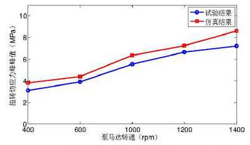
According to the test results of torsional shear strain of drive shaft, the torsional shear stress is calculated by formula and its peak value is calculated as the test result.The simulated torsional angles of gears 2 and 3 are applied as boundary conditions on the shaft section between them to obtain the torsional stress and calculate the peak value of the torsional stress.
The test results and simulation results of peak torsional shear stress of shaft section between gear 2 and gear 3 under different conditions and the errors between the two are shown in the figure.It can be seen that the torsional shear stress of shaft section between gear 2 and gear 3 increases approximately linearly with the increase of rotational speed, and the simulation results are basically in agreement with the test results.The maximum relative error between simulation results and test results under each operating condition is 17.9%.
For torsional shear stress, the main causes of errors between simulation results and test results are the same as the first four items in acceleration error analysis, and include the following aspects:
1.Oil holes and empty sensor lines exist on the drive shaft of the actual system, which results in local stress concentration. In the simulation, the shaft is simplified to a regular circular shaft, resulting in the test results under various conditions always greater than the simulation results.
2.Because the sampling frequency at the front of data acquisition is higher than that of dynamic strain gauge, a lot of system noise is mixed with valid data.
3.The sticking process of the strain gauge, the impedance of the connecting wire and the measuring error of the strainer itself will interfere with the test signal.