
As a widely adopted compact speed reduction solution, the cycloidal drive stands out for its high torque density, excellent overload capacity, and reliable operation. The operational health and longevity of a cycloidal drive are directly contingent upon the rationality, timeliness, and effectiveness of its fault diagnosis and handling procedures. This article delves into the fundamental operating principles of the cycloidal drive, provides a detailed analysis of common failure modes with systematic solutions, and extends the discussion to encompass mathematical modeling and predictive maintenance strategies to ensure optimal performance throughout its service life.
Fundamental Operating Principle of the Cycloidal Drive
The cycloidal drive, a specific variant of the cycloidal drive family, is a type of precision speed reducer based on the principle of single-stage或少齿差 planetary gearing, often classified as a K-H-V (Kurzweil-Hirt-Variant) mechanism. Its defining characteristic is the use of a lobed cycloidal disc (the planet gear) meshing with a ring of cylindrical pins (the ring gear or stator).
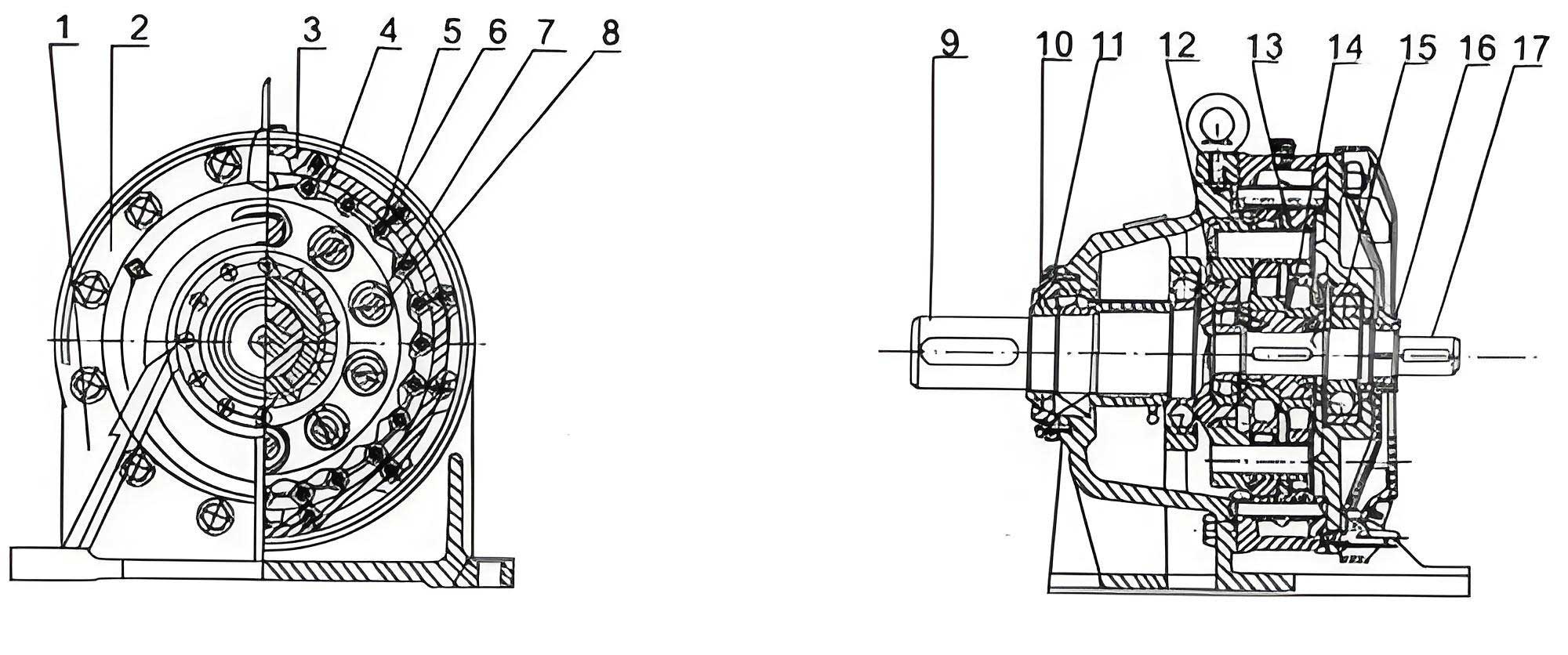
In a standard single-stage design, the primary components include a high-speed input shaft, an eccentric cam or bearing (constituting the ‘H’ or planet carrier), one or two cycloidal discs, a stationary pin wheel (ring gear) with multiple pin inserts (often fitted with rollers), and a low-speed output mechanism, typically a set of holes and rollers or a similar arrangement that converts the eccentric motion of the cycloidal disc into concentric rotation of the output shaft.
The kinematic action is elegant: The input shaft rotates the eccentric cam. This cam imparts an orbital motion to the cycloidal disc(s). Since the pin wheel is fixed, the lobes of the cycloidal drive disc are forced to engage sequentially with the stationary pins. This engagement causes the disc not only to orbit (revolve) around the central axis but also to rotate (spin) on its own axis in the opposite direction to the input rotation. The speed reduction is achieved through this compound motion. The precise geometry of the cycloidal profile ensures that multiple lobes are in contact simultaneously, distributing the load and providing high shock load resistance.
The theoretical speed reduction ratio (i) of a single-stage cycloidal drive is determined by the number of pins (Z_p) and the number of lobes on the cycloidal disc (Z_c), with the relationship given by:
$$ i = \frac{Z_p}{Z_p – Z_c} $$
Typically, the difference (Z_p – Z_c) is 1 for high-ratio reductions, resulting in a large reduction from a compact package. For example, if Z_p = 40 and Z_c = 39, the reduction ratio i = 40. The output mechanism then transmits this slow, reversed rotation of the cycloidal disc to the output shaft without altering its speed.
Systematic Fault Diagnosis and Remedial Actions for Cycloidal Drives
Despite their robustness, cycloidal drive units are susceptible to various faults influenced by operating conditions, installation accuracy, maintenance practices, and load profiles. A structured approach to diagnosis is crucial.
| Symptom / Fault | Primary Root Causes | Recommended Diagnostic & Corrective Actions |
|---|---|---|
| Excessive Temperature Rise (e.g., >80°C surface temperature) |
|
|
| Oil Leakage or Seepage |
|
|
| Abnormal Noise & Vibration (Growling, Clicking, Grinding) |
|
|
| Reduced Output Torque or Slipping |
|
|
Mathematical Modeling and Performance Analysis of Cycloidal Drives
A deeper understanding of cycloidal drive performance and failure modes can be gained through mathematical modeling. Key aspects include gear geometry, force distribution, and efficiency.
1. Cycloid Profile Generation: The lobe profile of the cycloidal disc is generated by a rolling circle of radius \( r_r \) on the inside of a base circle of radius \( R_b \). The parametric equations for the generated epicycloid (relative to the disc center) are:
$$ x(\theta) = (R_b – r_r)\cos\theta + r_r \cos\left(\frac{R_b – r_r}{r_r}\theta\right) $$
$$ y(\theta) = (R_b – r_r)\sin\theta – r_r \sin\left(\frac{R_b – r_r}{r_r}\theta\right) $$
where \( \theta \) is the rolling angle. This theoretical profile is then offset by the pin roller radius to obtain the conjugate working profile. The number of lobes \( Z_c \) is related to these radii.
2. Force and Torque Relationships: Assuming an ideal, frictionless system, the input torque \( T_{in} \) and output torque \( T_{out} \) are related by the reduction ratio and efficiency \( \eta \):
$$ T_{out} = \eta \cdot i \cdot T_{in} $$
The force acting on a single pin roller (\( F_{pin} \)) when the drive transmits \( T_{out} \) can be approximated by considering the number of simultaneously engaged lobes (\( n_{eng} \)) and the pitch radius of the pin circle (\( R_p \)):
$$ F_{pin} \approx \frac{T_{out}}{n_{eng} \cdot R_p} $$
This highlights the benefit of multiple engaged lobes in a cycloidal drive—the load is shared, leading to lower contact stresses and higher torque capacity.
3. Contact Stress Calculation (Hertzian Stress): Predicting wear and pitting failure requires calculating the contact stress between the cycloidal disc lobe and the pin roller. For two cylinders in contact (disc lobe approximated as a cylinder with radius of curvature \( \rho_c \) at the contact point), the maximum Hertzian contact pressure \( p_{max} \) is:
$$ p_{max} = \sqrt{\frac{F_{pin} E_{eq}}{\pi \rho_{eq} L}} $$
where:
\( E_{eq} \) is the equivalent Young’s modulus \( \left(\frac{1}{E_{eq}} = \frac{1-\nu_1^2}{E_1} + \frac{1-\nu_2^2}{E_2}\right) \),
\( \rho_{eq} \) is the equivalent radius of curvature \( \left(\frac{1}{\rho_{eq}} = \frac{1}{\rho_c} \pm \frac{1}{r_{roller}}\right) \) (sign depends on convex/concave contact),
and \( L \) is the effective contact length. Keeping \( p_{max} \) below the material’s allowable stress is critical for durability.
4. Mechanical Efficiency Estimation: The overall efficiency \( \eta \) of a cycloidal drive is a product of the efficiency of its sub-mechanisms:
$$ \eta = \eta_{bearing} \cdot \eta_{cycloid-mesh} \cdot \eta_{output-mech} $$
The mesh efficiency can be modeled considering sliding friction at the many contact points. An empirical approximation for a well-lubricated, run-in unit often falls in the range of 85% to 94% per stage. Efficiency drops significantly with wear or inadequate lubrication.
| Component | Primary Function | Typical Failure Mode | Impact on System |
|---|---|---|---|
| Cycloidal Disc | Transforms eccentric input motion into reduced-speed rotation via lobe-pin contact. | Lobe wear/pitting, cracking, fatigue spalling. | Increased backlash, noise, vibration, eventual loss of motion transmission. |
| Pin Rollers & Ring | Forms the stationary ring gear, providing multiple reaction points for the disc. | Roller wear, flattening, pin bending or breakage. | Increased clearance, uneven load sharing, catastrophic failure if pin breaks. |
| Eccentric Bearing | Supports the cycloidal disc and converts input shaft rotation into disc orbit. | Fatigue (spalling), brinelling, seizure, clearance increase. | Excessive vibration, heat generation, irregular disc motion, misalignment. |
| Output Mechanism (Wobble Bearings/Rolls) | Converts eccentric motion of the disc into concentric rotation of the output shaft. | Roller wear/breakage, hole wear in the disc, cage damage. | Loss of torque capacity, slippage, jerky output, complete drive lock-up. |
| Housing & Seals | Contains components, maintains lubrication, excludes contaminants. | Seal wear, gasket failure, casting porosity, fastener loosening. | Oil leakage, contamination ingress leading to accelerated internal wear. |
Predictive Maintenance and Life Extension Strategies
Moving beyond reactive repair, a predictive maintenance approach is vital for maximizing the uptime and life of a cycloidal drive in critical applications.
1. Condition Monitoring Parameters:
- Vibration Analysis: Regular spectral vibration analysis can detect early bearing defects (eccentric bearing), tooth mesh issues, and imbalance. Trends in vibration amplitude at characteristic frequencies are key indicators.
- Thermography: Periodic thermal imaging can identify abnormal hot spots on the reducer housing, indicating potential internal friction, overloading, or lubrication issues before they become severe.
- Oil Analysis: For larger units, periodic oil sampling and analysis can monitor wear metal concentrations (Fe, Cu from gears/bearings), particle count, and lubricant degradation (viscosity change, TBN depletion).
- Acoustic Emission Monitoring: Useful for detecting early-stage pitting and cracking in the high-stress contact zones of the cycloidal drive components.
2. Proactive Maintenance Actions:
- Scheduled Lubrication Management: Adhere strictly to OEM-recommended lubricant type, change intervals, and refill quantities. Use purging techniques for grease-lubricated models if applicable.
- Alignment Verification: Implement a routine schedule (e.g., semi-annually) to check and correct the alignment between the reducer and connected machinery.
- Fastener Re-torquing: After the first 500-1000 hours of operation, check and re-torque all housing and mounting fasteners to compensate for settling and gasket compression.
- Operational Logging: Maintain logs of operating hours, load cycles, and any abnormal events (shock loads, overloads) to correlate with condition data and predict remaining useful life.
In conclusion, the reliable and efficient operation of a cycloidal drive hinges on a profound understanding of its unique working principle, a systematic methodology for diagnosing its characteristic failure modes, and the implementation of a maintenance strategy that evolves from corrective to predictive. By integrating kinematic and stress analysis models with practical condition monitoring, engineers and maintenance personnel can not only troubleshoot effectively but also anticipate problems, thereby fully leveraging the inherent advantages of high torque density, compactness, and durability that the cycloidal drive technology offers. Ensuring these drives operate within their design parameters and are cared for proactively is the definitive approach to maximizing their service life and operational reliability in demanding industrial environments.