
The forged gear blank serves as a critical intermediate component in automotive transmission systems, particularly for spiral bevel gears in rear axles. Traditional manufacturing methods face limitations in material utilization, energy efficiency, and dimensional precision. This study establishes an integrated numerical framework combining finite element analysis (FEA) and experimental validation to optimize the entire manufacturing chain – from billet preparation to ring rolling and final forging – while addressing die failure mechanisms. The methodology significantly enhances production efficiency and extends die service life for forged gear blank applications.
Material Selection and Process Design
Low-carbon alloy steel 20CrMnTi (Chinese standard GB/T 3077) was selected for its balanced strength and forgeability. Chemical composition and physical properties govern billet design:
| Element | C | Si | Mn | Cr | Ti |
|---|---|---|---|---|---|
| Weight (%) | 0.17-0.23 | 0.17-0.37 | 0.80-1.10 | 1.00-1.30 | 0.04-0.10 |
| Property | Density (kg/m³) | Poisson’s Ratio | Elastic Modulus (GPa) |
|---|---|---|---|
| Value | 7800 | 0.25 | 207 |
Initial billet dimensions were calculated considering thermal expansion and machining allowances. The hot-forged volume \( V_f \) is derived from:
$$ V_f = V_d \times (1 + \delta) + V_l $$
where \( V_d \) is the final part volume (5,430,585 mm³), \( \delta \) is the oxidation loss (1%), and \( V_l \) is the flash volume. The billet diameter \( d_b \) is optimized through:
$$ d_b = \sqrt[3]{\frac{4V_b}{\pi m}} $$
with \( m \) (height-to-diameter ratio) set at 2.14, yielding \( d_b \) = 160 mm and length 342 mm.
Preforming Process Simulation
The preforming sequence – upsetting, pre-piercing, piercing, and sizing – was simulated in Deform-2D. Key process parameters included:
- Billet temperature: 1150°C
- Die preheat temperature: 150°C
- Shear friction coefficient: 0.3
- Upsetting speed: 6 mm/s
| Stage | Reduction (%) | Max. Load (MN) | Energy (kJ) |
|---|---|---|---|
| Upsetting | 76.3 | 3.41 | 332 |
| Pre-piercing | – | 0.97 | 96 |
| Piercing | – | 0.12 | 0.25 |
| Sizing | – | 6.78 | 64 |
Metal flow analysis confirmed streamline orientation parallel to the forged gear blank surface, eliminating folding defects. The optimized sizing die incorporated a 12° taper angle to enhance ring rolling stability.
Ring Rolling Optimization
Radial-axial ring rolling on D51-550 equipment transformed preforms into near-net-shape rings. The expansion ratio \( \lambda \) was maintained within 2–3 to prevent fishtail defects:
$$ \lambda = \frac{D_{i0}}{D_{if}} \leq \lambda_{\text{max}} = 5.5 \left( \frac{r_m}{R_1} \right) \left( 1 + \frac{R_1}{R_2} \right)^{0.5} $$
where \( D_{i0} \) and \( D_{if} \) are initial and final inner diameters, \( r_m \) is the mandrel radius, and \( R_1 \), \( R_2 \) are roll radii. Four preform heights were analyzed to quantify energy-defect relationships:
| Preform Height (mm) | Ring Pit Depth (mm) | Total Energy (MJ) | Max. Roll Force (MN) |
|---|---|---|---|
| 83 (+2) | 2.8 | 6.12 | 0.354 |
| 82 (+1) | 2.3 | 5.98 | 0.341 |
| 81 (Baseline) | 1.9 | 5.82 | 0.332 |
| 80 (-1) | 1.5 | 5.71 | 0.370 |
| 79 (-2) | 1.2 | 5.61 | 0.428 |
Height reduction decreased pit defects by 57% and total energy by 8.3%, confirming that lower preforms enhance dimensional accuracy while reducing power consumption in forged gear blank production.
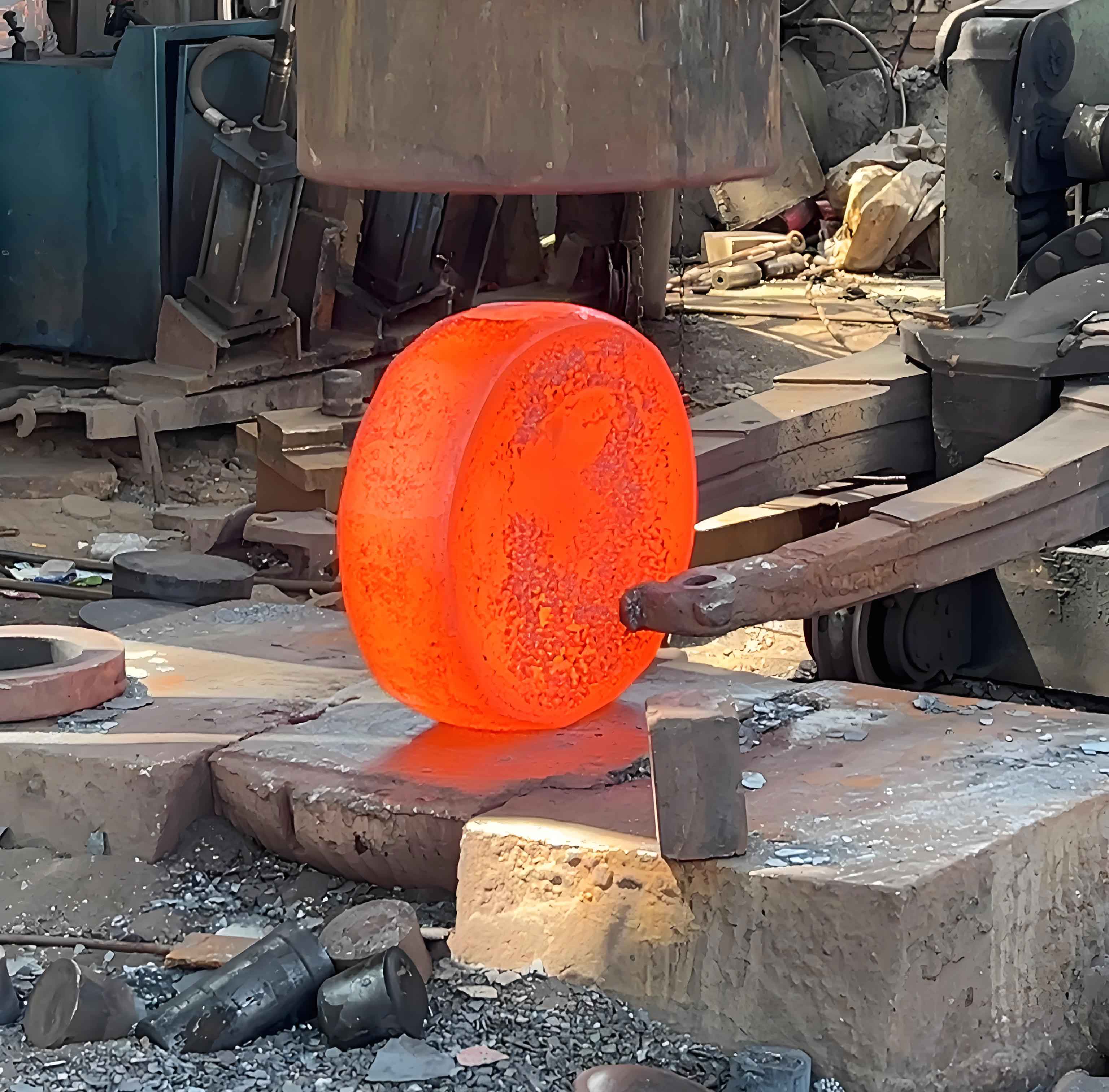
Closed-Die Forging and Die Wear Analysis
Final forging on a 63MN press employed AISI H-13 dies (46-50 HRC). A modified Archard model quantified die wear incorporating temperature-dependent hardness \( H(T) \) and wear coefficient \( k(T) \):
$$ \Delta W_{ij} = k(T) \frac{P_{ij} L_{ij}}{H(T)} $$
$$ H(T) = 9216 – 50.54T $$
$$ k(T) = (29.29 – 168\ln T) \times 10^{-6} $$
Orthogonal experiments optimized process parameters for minimized die wear and forging load:
| Factor | Level 1 | Level 2 | Level 3 |
|---|---|---|---|
| A: Die Hardness (HRC) | 50 | 55 | 60 |
| B: Forging Speed (mm/s) | 30 | 40 | 50 |
| C: Die Preheat (°C) | 150 | 200 | 250 |
| D: Billet Temp (°C) | 950 | 1000 | 1050 |
Optimal parameters (A3B1C2D3) reduced wear by 41.6% and forging load by 24.0%:
- Die hardness: 60 HRC
- Forging speed: 30 mm/s
- Die preheat: 200°C
- Billet temperature: 1050°C
Projected die life reached 8,196–12,295 cycles at 0.2–0.3 mm allowable wear, aligning with industrial benchmarks.
Thermal Fatigue Life Prediction
Stress concentrations at die corners (max. 3,000 MPa) and thermal cycling (ΔT = 439°C) drive fatigue failure. The Coffin-Manson equation estimated crack initiation life:
$$ \frac{\Delta \varepsilon}{2} = \frac{\sigma’_f – \sigma_m}{E} (2N)^b + \varepsilon’_f (2N)^c $$
Corrected fatigue strength exponent \( b^* \) accounted for stress gradients:
$$ b^* ≈ b + 0.137 \log(K_t / K_f) $$
where \( K_t \) = 2.0 (theoretical stress concentration) and \( K_f \) = 1.58 (fatigue notch factor). Predicted lives of 7,082 cycles (upper die) and 8,904 cycles (lower die) fell within the 8,000-cycle industrial average.
Conclusions and Industrial Implementation
This integrated approach demonstrates:
- Height-optimized preforms reduce ring rolling energy by 8.3% while minimizing pit defects
- Parameter optimization decreases forging loads by 24% and extends die life by 41.6%
- Thermal fatigue predictions correlate with actual service performance
The validated framework enables precision manufacturing of high-integrity forged gear blank components with extended tooling longevity, establishing new benchmarks for automotive transmission component production.