
In my extensive experience as a materials engineer, I have encountered numerous instances where heat treatment defects significantly impact the performance and longevity of critical components. Heat treatment is a vital process in metallurgy, used to alter the physical and sometimes chemical properties of materials, primarily metals and alloys. However, despite its importance, heat treatment defects are common and can lead to catastrophic failures if not properly managed. These heat treatment defects arise from various factors, including improper heating, cooling, or environmental conditions during the process. Throughout this article, I will delve into the types, causes, and control strategies for heat treatment defects, drawing from practical cases and theoretical insights. The goal is to provide a detailed guide that helps professionals mitigate these issues effectively.
Heat treatment defects can manifest as dimensional changes, cracks, residual stresses, oxidation, decarburization, and microstructural anomalies. Each of these heat treatment defects has unique origins and consequences. For example, dimensional distortions, such as those seen in large gear shafts, are among the most prevalent heat treatment defects. In such cases, components like gears or shafts undergo significant shape changes after quenching, leading to misalignment and reduced functionality. The root causes often involve thermal gradients and phase transformations during cooling. To understand this better, consider the fundamental equations governing heat transfer and stress development. The heat conduction equation is given by:
$$ \frac{\partial T}{\partial t} = \alpha \nabla^2 T $$
where \( T \) is temperature, \( t \) is time, and \( \alpha \) is thermal diffusivity. This equation helps model the temperature distribution during heating and cooling, which is crucial for predicting heat treatment defects. Additionally, the stress due to thermal expansion can be expressed as:
$$ \sigma = E \beta \Delta T $$
where \( \sigma \) is stress, \( E \) is Young’s modulus, \( \beta \) is the coefficient of thermal expansion, and \( \Delta T \) is the temperature difference. These formulas highlight how rapid cooling can induce high stresses, leading to heat treatment defects like cracking or warping.
Another critical aspect of heat treatment defects is microstructural changes. During processes like carburizing or quenching, the formation of undesirable phases can occur. For instance, retained austenite or excessive carbide precipitation can weaken the material. In one project, I analyzed a T8 steel sample austenitized at 320°C for 230 seconds, which resulted in a mixture of lower bainite, martensite, and retained austenite. This microstructure, if not controlled, can lead to heat treatment defects such as reduced hardness or brittleness. Similarly, T12 steel’s equilibrium structure of pearlite and cementite network can be altered by improper heat treatment, causing heat treatment defects like spheroidization or graphitization. To quantify these effects, we can use phase transformation kinetics. The Johnson-Mehl-Avrami-Kolmogorov (JMAK) equation describes the fraction of transformed phase:
$$ f = 1 – \exp(-k t^n) $$
where \( f \) is the transformed fraction, \( k \) is a rate constant, \( t \) is time, and \( n \) is the Avrami exponent. This model aids in predicting microstructural evolution and preventing heat treatment defects related to incomplete or over-transformation.
To systematically categorize heat treatment defects, I have compiled a table summarizing common types, their causes, and typical mitigation measures. This table serves as a quick reference for identifying and addressing these issues in practice.
| Type of Heat Treatment Defect | Primary Causes | Common Mitigation Strategies |
|---|---|---|
| Dimensional Distortion | Uneven heating/cooling, phase change stresses | Use of fixtures, controlled cooling, pre-allowed shrinkage |
| Cracking | High thermal stresses, martensitic transformation | Preheating, slower quenching, isothermal quenching |
| Oxidation and Decarburization | Exposure to air at high temperatures | Protective atmospheres, coating with anti-scale compounds |
| Soft Spots | Inadequate quenching, poor heat transfer | Agitated quench baths, proper part orientation |
| Residual Stresses | Non-uniform cooling, transformation plasticity | Stress relieving tempering, shot peening |
| Microstructural Inhomogeneity | Improper soaking time, incorrect temperature | Precise temperature control, diffusion annealing |
As evident from the table, heat treatment defects are diverse, but many share common root causes. In my work, I have found that digital imaging techniques greatly assist in detecting and analyzing these heat treatment defects. For example, using a 16-megapixel digital microscope, I can capture high-resolution images of microstructures, revealing details like bainite formations or carbide networks. This technology replaces traditional darkroom methods, reducing environmental pollution and speeding up analysis. The digital images allow for precise measurement of phase proportions and defect sizes, which is essential for quantifying heat treatment defects. The image below illustrates a typical heat treatment defect observed in a steel sample, showcasing the importance of visual inspection in quality control.
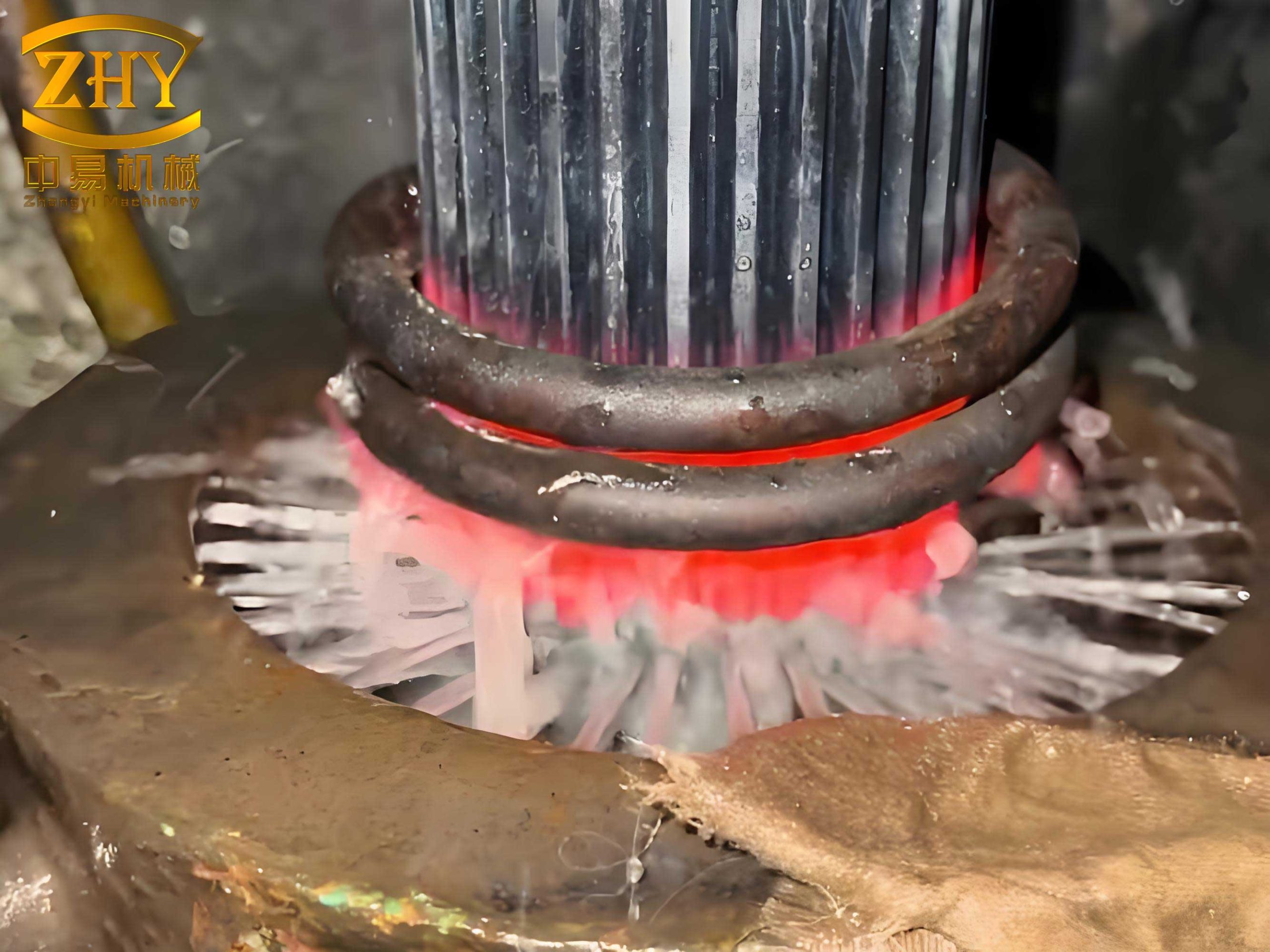
In one notable case involving a large gear shaft, heat treatment defects like severe distortion were a major concern. The shaft, with a diameter of 500–600 mm and a module of 22, required carburizing to a depth of 5.0–5.5 mm. After oil quenching at 860°C, the shaft exhibited a saddle-shaped distortion, with the middle section shrinking by up to 2.0 mm. This heat treatment defect arose from combined thermal and transformational stresses. To address this, I implemented an isothermal quenching process in a nitrate salt bath at 180–204°C, along with a pre-allowed shrinkage of 1.5 mm. The quenching stress during martensitic transformation can be modeled using the following equation:
$$ \sigma_{tr} = V_m \Delta G \epsilon $$
where \( \sigma_{tr} \) is transformational stress, \( V_m \) is molar volume, \( \Delta G \) is Gibbs free energy change, and \( \epsilon \) is strain. By lowering the quenching temperature and using isothermal holds, we reduced the cooling rate, minimizing these stresses and thus controlling heat treatment defects. The process involved steps like carburizing at 930°C for 120 hours, high-temperature tempering at 680°C, and final tempering at 200°C and 180°C. This approach successfully limited distortion to under 1.5 mm, demonstrating how tailored processes can mitigate heat treatment defects.
Beyond distortion, other heat treatment defects like cracking are equally critical. Cracks often initiate from stress concentrations during rapid cooling. The risk of cracking increases with higher carbon content and section thickness. To predict cracking susceptibility, we can use the concept of critical stress intensity factor \( K_{IC} \), related to fracture toughness. For a given material, if the induced stress exceeds \( K_{IC} \), cracks may propagate. The formula for stress intensity in a semi-elliptical surface crack is:
$$ K_I = \sigma \sqrt{\pi a} \cdot F $$
where \( K_I \) is stress intensity, \( \sigma \) is applied stress, \( a \) is crack depth, and \( F \) is a geometry factor. By controlling cooling rates and using additives in quenchants, we can keep stresses below critical levels, preventing heat treatment defects like cracking. In practice, I often recommend polymer quenchants or interrupted quenching for sensitive parts to reduce thermal shocks.
Oxidation and decarburization are surface-related heat treatment defects that degrade material properties. During heating in air, oxygen reacts with iron to form oxides, while carbon diffuses out, causing a soft surface layer. This can be quantified using Fick’s laws of diffusion. For decarburization, the carbon concentration profile over time is given by:
$$ C(x,t) = C_0 \cdot \text{erfc}\left( \frac{x}{2\sqrt{Dt}} \right) $$
where \( C(x,t) \) is carbon concentration at depth \( x \) and time \( t \), \( C_0 \) is initial concentration, \( D \) is diffusion coefficient, and erfc is the complementary error function. To combat these heat treatment defects, I use protective atmospheres like endothermic gas or vacuum furnaces. Additionally, coatings such as boron nitride can be applied to shield parts during heat treatment.
Digital image analysis has revolutionized the study of heat treatment defects. With systems offering 16-megapixel resolution, I can store and analyze vast amounts of microstructural data. This allows for statistical evaluation of defect distributions, such as measuring the percentage of retained austenite or carbide size. The use of software tools enables automatic detection of anomalies, reducing human error in identifying heat treatment defects. For instance, in a sample with lower bainite and equilibrium structures, image analysis can quantify phase fractions using pixel intensity thresholds. The relationship between microstructure and properties can be expressed via Hall-Petch equation for strength:
$$ \sigma_y = \sigma_0 + k_y d^{-1/2} $$
where \( \sigma_y \) is yield strength, \( \sigma_0 \) is friction stress, \( k_y \) is a constant, and \( d \) is grain size. By correlating digital images with mechanical tests, we can better understand how heat treatment defects affect performance.
In educational settings, digital microscopy aids in teaching about heat treatment defects. Instructors can display real-time images on large screens, pointing out features like martensite needles or deformation twins. This interactive approach enhances learning and helps students accurately identify heat treatment defects. From my perspective, this technology is invaluable for training new engineers and technicians, ensuring they recognize and address these issues early in production.
To further elaborate on control strategies, I often employ computational modeling to simulate heat treatment processes. Finite element analysis (FEA) can predict temperature fields and stress distributions, allowing for optimization before actual treatment. The governing equation for thermo-mechanical coupling is:
$$ \rho c_p \frac{\partial T}{\partial t} = \nabla \cdot (k \nabla T) + Q $$
where \( \rho \) is density, \( c_p \) is specific heat, \( k \) is thermal conductivity, and \( Q \) is heat generation rate from phase transformations. By inputting material properties and boundary conditions, FEA software can forecast potential heat treatment defects, enabling proactive adjustments. For example, in the gear shaft case, simulations showed that isothermal quenching reduced peak stresses by 30%, aligning with experimental results.
Another common heat treatment defect is residual stress, which can lead to premature fatigue failure. Residual stresses arise from non-uniform plastic deformation during cooling. They can be measured using techniques like X-ray diffraction or hole-drilling, but prevention is key. Stress-relief tempering is a standard method, where parts are heated to below the lower critical temperature and held to allow stress relaxation. The kinetics of stress relaxation can be described by:
$$ \sigma(t) = \sigma_0 \exp(-t/\tau) $$
where \( \sigma(t) \) is stress at time \( t \), \( \sigma_0 \) is initial stress, and \( \tau \) is relaxation time constant. By incorporating such tempering cycles, we can significantly reduce residual stresses, mitigating this type of heat treatment defect.
In summary, heat treatment defects are multifaceted challenges that require a deep understanding of materials science and process engineering. Through my career, I have learned that a combination of theoretical knowledge, practical adjustments, and advanced technologies is essential for control. Key strategies include precise temperature control, tailored cooling methods, use of protective atmospheres, and digital monitoring. The table below expands on mitigation techniques for specific heat treatment defects, based on my experiences.
| Heat Treatment Defect | Recommended Mitigation Technique | Expected Outcome |
|---|---|---|
| Distortion in Large Shafts | Isothermal quenching in nitrate salt, pre-allowed shrinkage | Distortion < 1.5 mm, stable dimensions |
| Surface Cracking | Preheating to 650°C, use of polymer quenchants | Reduced crack incidence, improved toughness |
| Decarburization in Carburized Parts | Atmosphere control with carbon potential of 0.8-1.2% | Uniform carburized layer, hardness > 60 HRC |
| Retained Austenite Excess | Sub-zero treatment or multiple tempering cycles | Retained austenite < 5%, enhanced dimensional stability |
| Soft Spots in Quenched Parts | Agitated oil quench, uniform part orientation | Hardness variation < 2 HRC across surface |
| Microstructural Banding | Homogenization annealing at 1100°C for extended times | Uniform microstructure, improved ductility |
Looking ahead, the field of heat treatment is evolving with innovations like additive manufacturing and artificial intelligence. These technologies offer new ways to monitor and prevent heat treatment defects. For instance, AI algorithms can analyze real-time sensor data to adjust furnace parameters dynamically, minimizing deviations that lead to heat treatment defects. Additionally, advanced materials like high-entropy alloys present unique challenges, as their heat treatment responses differ from traditional steels. Research into their phase stability and transformation kinetics is crucial to avoid novel heat treatment defects.
In conclusion, heat treatment defects remain a central concern in manufacturing, but with systematic approaches, they can be effectively managed. From dimensional distortions to microstructural anomalies, each defect has identifiable causes and solutions. By leveraging formulas for stress and diffusion, utilizing digital imaging for analysis, and implementing controlled processes like isothermal quenching, we can reduce the incidence of heat treatment defects. As I continue my work, I emphasize the importance of continuous learning and adaptation, as new materials and processes will always bring fresh challenges in combating heat treatment defects. Ultimately, a proactive stance on quality control and process optimization is key to ensuring component reliability and performance in industrial applications.
To reinforce the concepts, let’s consider a few more mathematical models relevant to heat treatment defects. The quench severity factor, \( H \), is used to characterize cooling efficiency and predict hardness profiles. It is defined as:
$$ H = \frac{k}{2h} $$
where \( k \) is thermal conductivity and \( h \) is heat transfer coefficient. Higher \( H \) values indicate severer quenching, which can increase the risk of heat treatment defects like cracking. Therefore, selecting an appropriate \( H \) through quenchant choice is vital. Another useful model is the TTT (Time-Temperature-Transformation) diagram, which plots transformation start and finish times against temperature. By avoiding nose regions where transformations are rapid, we can design processes that minimize undesirable phases and associated heat treatment defects. For example, for a eutectoid steel, the TTT diagram shows bainite and pearlite formation ranges; quenching quickly through these zones to form martensite requires careful control to prevent defects.
In practice, I often conduct failure analyses on components with heat treatment defects. Using techniques like scanning electron microscopy (SEM) and energy-dispersive X-ray spectroscopy (EDS), I can identify root causes such as inclusions or segregation that exacerbated defects. For instance, sulfur inclusions can act as stress raisers, promoting cracks during quenching. The inclusion size effect on stress concentration is given by:
$$ K_t = 1 + 2\sqrt{\frac{a}{\rho}} $$
where \( K_t \) is stress concentration factor, \( a \) is inclusion length, and \( \rho \) is tip radius. This highlights how material purity influences heat treatment defects. Therefore, specifying clean steels with low impurity levels is a preventive measure against such heat treatment defects.
Finally, education and training play a crucial role in reducing heat treatment defects. By teaching engineers about the underlying principles and common pitfalls, we can foster a culture of quality. Workshops on digital image analysis and simulation tools empower teams to proactively address heat treatment defects. In my view, sharing knowledge through articles like this is essential for advancing the field and minimizing the impact of heat treatment defects across industries.