
Gear hobbing stands as one of the most prevalent and efficient continuous gear generation processes in modern manufacturing. As a fundamental pillar in power transmission systems, gears demand high precision, durability, and surface integrity. This article delves into the core principles of gear hobbing, explores its mathematical foundation, examines advanced variants including innovative surface enhancement techniques, and discusses its critical role in producing high-performance components for demanding applications. The process, characterized by its versatility and productivity, is essential for meeting the stringent requirements of industries such as automotive, aerospace, and heavy machinery.
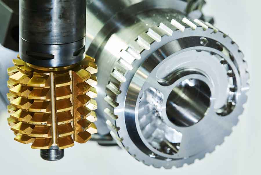
The essence of gear hobbing lies in the simulated meshing of a cutting tool, known as a hob, with a gear blank. The hob is a helical cutting tool whose teeth are arranged along a helix. During the gear hobbing operation, both the hob and the workpiece rotate in a synchronized manner, with their axes set at a specific angle determined by the helix angles of the hob and the desired gear. The process involves a series of generating motions that progressively carve the gear teeth into the blank. The efficiency of gear hobbing is attributed to its continuous cutting action, which allows for high material removal rates and excellent surface finishes. A critical aspect of modern gear hobbing is the focus on post-process surface integrity, which directly influences fatigue life, wear resistance, and noise-vibration-harshness (NVH) performance. This has led to the development of combined and hybrid processes that integrate hobbing with subsequent surface enhancement techniques.
Fundamental Kinematics and Geometry of Gear Hobbing
The kinematics of the gear hobbing process are defined by the coordinated rotational speeds of the hob and the workpiece. The fundamental relationship governing this synchronized motion is given by the gear ratio between the hob and the blank. For a single-start hob, the relationship is:
$$ \frac{N_w}{N_h} = \frac{n_h}{n_w} = \frac{Z_w}{K} $$
Where:
$N_w$ is the rotational speed of the workpiece (rpm),
$N_h$ is the rotational speed of the hob (rpm),
$Z_w$ is the number of teeth on the workpiece gear,
$K$ is the number of gashes (threads) on the hob. For a single-start hob, $K=1$.
The feed motion, which can be axial, radial, or tangential, determines the rate at which the hob advances along or into the workpiece. The cutting speed $V_c$ is a critical parameter, calculated from the hob’s rotational speed and its pitch diameter $D_h$:
$$ V_c = \pi D_h N_h $$
The geometry of the hob tooth is complex and directly imprints on the generated gear profile. The hob can be considered as a rack whose teeth have been wrapped around a cylinder. The basic rack profile, typically conforming to a standard like ISO 53, defines the shape of the gear teeth. The mathematical definition of an involute tooth profile, which is the standard for modern gears, is derived from the geometry of a base circle. The coordinates $(x, y)$ of an involute curve can be expressed parametrically using the pressure angle $\alpha$ and the base circle radius $r_b$:
$$ x = r_b (\cos \theta + \theta \sin \theta) $$
$$ y = r_b (\sin \theta – \theta \cos \theta) $$
where $\theta$ is the roll angle (in radians). The hob is designed to generate this involute profile through its precise cutting edges and the generating motion.
| Parameter | Symbol | Typical Range/Value | Influence on Process |
|---|---|---|---|
| Hob Rotational Speed | $N_h$ | 100 – 3000 rpm | Determines cutting speed, productivity, tool life. |
| Axial Feed | $f_a$ | 0.5 – 3.0 mm/rev | Affects chip load, surface finish, cutting forces. |
| Hob Module | $m_n$ | 1 – 20 mm | Defines tooth size. Must match gear module. |
| Number of Hob Starts | $K$ | 1 – 4 | Higher starts increase productivity but may affect finish. |
| Setting Angle | $\Sigma$ | $\Sigma = \beta_h \pm \beta_g$ | Angle between hob and gear axes, crucial for correct tooth generation. |
Cutting Forces and Mechanics in Gear Hobbing
Understanding the cutting forces in gear hobbing is vital for machine tool design, stability, and predicting tool wear. The force system is three-dimensional and dynamic, varying as each hob tooth engages and exits the cut. The total cutting force $\vec{F}$ can be resolved into three primary orthogonal components:
– Tangential Force ($F_t$): Acts in the direction of the hob’s cutting velocity, responsible for the main cutting power consumption.
– Radial Force ($F_r$): Acts perpendicular to the hob axis and towards its center, influencing hob deflection and accuracy.
– Axial Force ($F_a$): Acts parallel to the hob axis, particularly significant for helical gears due to the helix angle.
These forces can be estimated using mechanistic models based on the uncut chip geometry. The average tangential force per tooth can be approximated as:
$$ F_{t, avg} = k_c \cdot A_c $$
where $k_c$ is the specific cutting force (a material-dependent parameter) and $A_c$ is the average cross-sectional area of the undeformed chip. For gear hobbing, the chip area is a function of feed per tooth $f_z$, depth of cut $a_p$, and the engagement geometry. A more comprehensive model considers the local chip thickness $h(\phi)$, which varies with the rotation angle $\phi$ of the hob. The instantaneous tangential force can be expressed as:
$$ F_t(\phi) = K_{tc} \cdot b \cdot h(\phi) + K_{te} \cdot b $$
Here, $K_{tc}$ and $K_{te}$ are the cutting and edge force coefficients, respectively, $b$ is the instantaneous width of cut, and $h(\phi)$ is the instantaneous chip thickness. The radial and axial forces are often related to the tangential force through empirical ratios $\lambda_r$ and $\lambda_a$:
$$ F_r(\phi) \approx \lambda_r F_t(\phi), \quad F_a(\phi) \approx \lambda_a F_t(\phi) $$
These forces induce vibrations, which can lead to deviations in gear tooth geometry and surface finish irregularities. Advanced gear hobbing machines employ robust structures and damping systems to mitigate these effects.
Advanced and Hybrid Gear Hobbing Processes
To meet ever-increasing demands for performance, efficiency, and surface quality, several advanced variants of conventional gear hobbing have been developed. These include dry hobbing, high-speed hobbing, and power-skiving. However, a particularly significant development is the integration of surface enhancement directly with or immediately after the gear hobbing process to improve the surface integrity of the tooth flanks.
1. Hard Gear Hobbing: This process involves hobbing gears after they have been case-hardened (e.g., to 58-62 HRC). It eliminates distortions caused by heat treatment and achieves high precision. It requires extremely hard and wear-resistant hob materials like solid carbide or advanced coated carbide, and often operates at lower cutting speeds than soft hobbing.
2. High-Speed Dry Gear Hobbing: Driven by environmental and economic factors, this process eliminates cutting fluids. It relies on specialized tool coatings (e.g., TiAlN, AlCrN), optimized chip evacuation, and controlled thermal management to succeed at very high cutting speeds, significantly boosting productivity.
3. Power Skiving: An interrupted gear cutting process where a skiving tool, similar to a shaped hob, meshes with the workpiece at a crossed-axis angle. It is highly productive for internal gears and can be performed on multitasking machines. The kinematics are more complex than standard gear hobbing but offer distinct advantages for certain part geometries.
4. Surface-Enhancement-Integrated Hobbing: The most relevant category to the provided context involves combining the material removal action of gear hobbing with a surface plastic deformation process. One innovative approach is the application of ultrasonic vibrations to the hobbing process or a subsequent rolling operation. In a conceptual “ultrasonic-assisted gear hobbing” setup, high-frequency vibrations (typically >20 kHz) with low amplitude (microns) are superimposed on the cutting motion of the hob. The benefits theorized include:
– Reduction in cutting forces due to the intermittent contact and softening effect.
– Improved chip breaking and evacuation.
– Potential for better surface finish and reduced residual tensile stresses.
– Extended tool life.
More directly, the process described in the initial text—Longitudinal-Torsional Ultrasonic Rolling (LTUR)—is a potent post-hobbing surface enhancement technique. It is not gear hobbing per se, but a critical allied process applied to gears, often after they have been hobbed and heat-treated. The principle involves using a hardened tool gear, excited with ultrasonic vibrations, to roll against the workpiece gear under a controlled load (damping torque). The ultrasonic impact combined with rolling induces severe plastic deformation at the surface, improving fatigue strength.
Mechanism of Surface Enhancement via Ultrasonic Rolling
The effectiveness of processes like Ultrasonic Surface Rolling (USR) or LTUR lies in their ability to induce beneficial compressive residual stresses and work-harden the near-surface layer. The mechanics can be analyzed using contact theory. When the tool gear (or a roller) contacts the workpiece gear tooth under load $F_n$, Hertzian contact pressure develops. The maximum contact pressure $p_0$ at the center of the contact patch is given by:
$$ p_0 = \sqrt{\frac{F_n E^*}{\pi R^* b}} $$
where $E^*$ is the equivalent elastic modulus, $R^*$ is the equivalent radius of curvature at the contact point, and $b$ is the face width. The equivalent quantities are calculated as:
$$ \frac{1}{E^*} = \frac{1-\nu_1^2}{E_1} + \frac{1-\nu_2^2}{E_2}, \quad \frac{1}{R^*} = \frac{1}{R_1} \pm \frac{1}{R_2} $$
During ultrasonic rolling, a dynamic force $F_{dyn}(t)$ from the vibration is superimposed on the static load $F_n$. This dynamic component can be approximated as related to the kinetic energy of the oscillating mass. The total instantaneous load $F_{total}(t) = F_n + F_{dyn}(t)$ can be significantly higher than $F_n$ alone, causing the peak contact pressure to periodically exceed the yield strength of the material. This leads to cyclic plastic deformation. After the tool passes, the elastic core of the material attempts to recover, but the plastically deformed surface layer is constrained, resulting in a state of residual compressive stress $\sigma_{res}$ in the surface and subsurface layers.
The depth of the compressive layer and the magnitude of $\sigma_{res}$ depend on parameters like static load, ultrasonic amplitude, and the number of passes. The induced compressive stress directly counteracts the tensile stresses that initiate fatigue cracks, thereby dramatically improving the gear’s bending and contact fatigue life. Furthermore, the plastic deformation refines the surface grain structure, closes micro-cracks and pores, and reduces surface roughness peaks, leading to the improvements observed in the initial study: significant increases in surface hardness and reductions in roughness.
| Surface Integrity Parameter | Conventional Gear Hobbing/Finishing | Ultrasonic-Assisted Rolling/Enhancement | Typical Improvement |
|---|---|---|---|
| Surface Roughness, $R_a$ | 0.8 – 3.2 μm | 0.4 – 1.6 μm | Reduction of 30% – 60% |
| Residual Stress ($\sigma_{res}$) at Surface | Slightly tensile or low compressive | High compressive (-800 to -1200 MPa) | Introduction/Increase of compressive stress |
| Microhardness (HV) | Base material hardness (e.g., 300 HV) | Severe plastic deformation layer (e.g., 400-450 HV) | Increase of 30% – 50% |
| Fatigue Strength | Baseline | Significantly enhanced | Improvement of 50% – 100%+ |
| Process Nature | Material removal (subtractive) | Material displacement (plastic deformation) | Surface densification and strengthening |
Process Modeling and Optimization in Gear Hobbing
Advanced modeling techniques are indispensable for optimizing gear hobbing processes, predicting outcomes, and reducing costly trial-and-error. Finite Element Analysis (FEA) is extensively used to simulate the complex thermo-mechanical events during cutting and subsequent surface treatments.
FEA of Gear Hobbing: 3D transient thermo-mechanical FEA models can simulate the interaction between a single hob tooth and the workpiece. The model requires defining:
– Material constitutive laws (e.g., Johnson-Cook model for high strain rates):
$$ \sigma_y = \left[A + B \epsilon^n \right] \left[1 + C \ln \frac{\dot{\epsilon}}{\dot{\epsilon}_0} \right] \left[1 – \left( \frac{T-T_{room}}{T_{melt}-T_{room}} \right)^m \right] $$
– Friction conditions at the tool-chip interface.
– Accurate meshing with refinement in the shear zone.
– Simulating the tool path and material removal.
Outputs include cutting forces, temperatures, stresses, and predictions of white layer formation or residual stresses.
FEA of Ultrasonic Rolling: As demonstrated in the initial research, FEA can model the dynamic contact. The simulation often involves two steps: first, an explicit dynamic analysis to apply the oscillating load and induce plastic deformation; second, an implicit static analysis to release the load and compute the resulting residual stress state. This helps in understanding the depth of the affected zone and the stress distribution.
Furthermore, analytical models based on gear geometry and kinematics are used for process planning. Software solutions calculate optimal machine settings (speeds, feeds, axial positions), simulate the generated tooth form to predict deviations, and plan hob regrinding schedules to maintain accuracy. The goal of all modeling is to achieve a specified Quality Class (e.g., ISO 1328) with maximum efficiency and tool life.
Material Considerations and Tooling for Gear Hobbing
The selection of workpiece material and hob tooling is critical for successful gear hobbing operations. Common gear materials include:
– Case-Carburizing Steels (e.g., SAE 8620, 20MnCr5): The industry standard for high-performance gears. They are hobbed in the “soft” state (~30 HRC) and then case-hardened to achieve a hard, wear-resistant surface with a tough core.
– Through-Hardening Steels (e.g., SAE 4140, 4340): Used where core strength is paramount. They are hobbed in an annealed or normalized state and then hardened and tempered.
– Nitriding Steels (e.g., 31CrMoV9): Hobbed and heat-treated before a low-temperature nitriding process that imparts high surface hardness with minimal distortion.
– Non-Ferrous Alloys: Such as brass, bronze, and aluminum, are hobbed for specific applications requiring corrosion resistance or low weight.
The hob is the heart of the gear hobbing process. Modern hobs are engineered masterpieces:
- Material: High-Speed Steel (HSS) is common for general-purpose soft gear hobbing. Powder Metallurgy (PM) HSS offers better wear resistance. Solid carbide or carbide-tipped hobs are essential for hard gear hobbing and high-productivity dry hobbing.
- Coatings: Physical Vapor Deposition (PVD) coatings like TiAlN, AlCrN, and TiSiN are standard. They reduce friction, increase hardness, and provide thermal barriers, drastically extending tool life, especially in dry cutting conditions.
- Design: Hobs can be single- or multi-start, with gashes optimized for chip formation and evacuation. The lead, rake angles, and relief angles are carefully designed for specific materials and cutting conditions.
Tool wear mechanisms in gear hobbing include flank wear, crater wear on the rake face, and chipping. Monitoring wear is essential for maintaining gear quality. The integration of vibration analysis or acoustic emission sensors on hobbing machines is an emerging trend for real-time process monitoring and predictive maintenance.
Future Trends and Conclusions
The future of gear hobbing is oriented towards greater intelligence, sustainability, and integration. Key trends include:
- Digitalization and Industry 4.0: Gear hobbing machines are becoming nodes in smart factories. They are equipped with sensors collecting data on forces, vibrations, temperature, and power consumption. This data is used for adaptive control, predictive maintenance, and traceability, ensuring consistent quality and minimizing unplanned downtime.
- Dry and Minimum Quantity Lubrication (MQL) Gear Hobbing: The push for environmentally friendly manufacturing will continue to drive the adoption and refinement of dry hobbing and MQL, reducing waste disposal costs and health hazards associated with cutting fluids.
- Ultra-High-Speed and High-Accuracy Gear Hobbing: Advancements in machine tool dynamics, spindle technology, and control systems will enable even higher cutting speeds while maintaining or improving accuracy. This demands corresponding advances in hob materials and coatings.
- Integration of Finishing and Enhancement: The line between gear cutting and finishing will blur further. Processes like power honing or innovative methods like the discussed ultrasonic rolling may be integrated into single machine platforms or tightly coupled production cells, reducing handling and lead times while guaranteeing superior surface integrity.
- Advanced Modeling and Simulation: The use of digital twins for the entire gear manufacturing process, from hobbing to heat treatment to finishing, will become more prevalent. This allows for virtual optimization and problem-solving before physical production begins.
In conclusion, gear hobbing remains a dynamic and evolving field fundamental to precision engineering. From its well-established kinematic principles to the cutting-edge integration of surface enhancement techniques like ultrasonic rolling, the process continues to adapt to meet the challenges of modern industry. The synergy between traditional gear hobbing for form generation and advanced post-process treatments for surface integrity is key to manufacturing gears that are not only geometrically accurate but also possess the durability and performance required for the most demanding applications. The ongoing research and development in tooling, machine tools, process modeling, and hybrid techniques ensure that gear hobbing will continue to be a cornerstone of power transmission manufacturing for the foreseeable future.