
In my extensive experience with power transmission systems, the cycloidal drive stands out for its unique operating principle and robust performance. Based on the principles of small tooth difference planetary transmission, this mechanism utilizes the engaging action between a cycloidal disc and stationary needle rollers to achieve high reduction ratios within a compact volume. Its widespread adoption across industries, from heavy machinery to precision automation, is a testament to its efficiency and durability. However, like any mechanical system, a cycloidal drive is susceptible to failures primarily stemming from lubrication neglect, overload, improper installation, fastener loosening, and inadequate maintenance. These issues, if left unaddressed, can escalate from mere inefficiencies—such as wasted lubricant and noise pollution—to catastrophic breakdowns causing complete production line stoppages. My objective here is to provide a detailed, first-person perspective on systematically diagnosing and rectifying common faults in cycloidal drives, ensuring their reliable and continuous operation.
Fundamental Operating Principles and Failure Modes
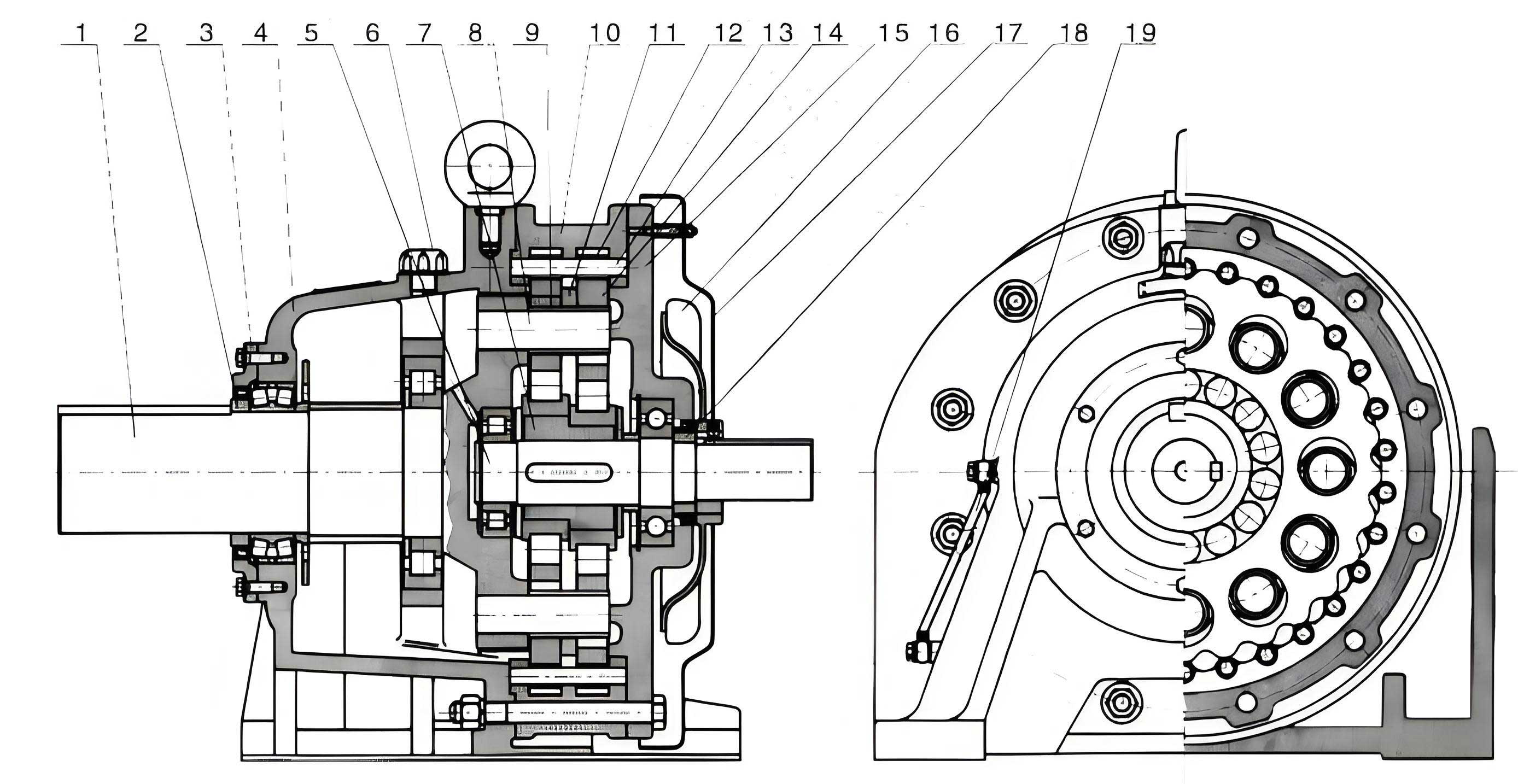
To effectively troubleshoot a cycloidal drive, one must first understand its core kinematics. The heart of the system is the cycloidal disc, which features a lobed profile defined mathematically. As an eccentric input shaft rotates, it imparts an eccentric motion to this disc. The disc’s lobes mesh with a ring of stationary needle rollers housed in the pin housing. For each full rotation of the input eccentric, the cycloidal disc undergoes a backward rotational “wobble” equal to the difference between its number of lobes (N_c) and the number of needle rollers (N_p). This motion is then translated into a slow, continuous output rotation via a set of pins (or rollers) and holes in the output flange.
The fundamental speed reduction ratio (i) of a single-stage cycloidal drive is given by:
$$ i = \frac{N_p}{N_p – N_c} $$
Where $N_p$ is the number of needle rollers (pins) and $N_c$ is the number of lobes on the cycloidal disc. Typically, $N_c = N_p – 1$, leading to a high reduction ratio $i = N_p$.
The primary internal load-bearing components include the cycloidal discs (often used in pairs for balance), the needle rollers and their sleeves, the eccentric bearing (also called the rotating arm bearing), and the output mechanism pins. Failure modes are intrinsically linked to these components and their interactions under stress, poor lubrication, or misalignment.
Systematic Fault Analysis Methodology
My approach to diagnosing a suspect cycloidal drive always begins with non-invasive checks before proceeding to disassembly.
1. Initial Operational Check and Transmission Fault Analysis
The first step is a manual assessment. I rotate the input shaft or the connected motor’s fan. A smooth, consistent rotation feeling is a positive initial sign. I then observe the output shaft; it should rotate slowly in the opposite direction. Successful completion of this test generally indicates that the transmission components are intact under no-load conditions.
Next, I check for excessive backlash, which is a key indicator of wear. I firmly hold the input stationary and rock the output shaft back and forth. The angular movement felt is the total system backlash. A minimal, barely perceptible clearance is acceptable for an aged unit. However, significant backlash points to advanced wear in the cycloidal disc lobes, needle sleeves, or the output pin mechanism. A drive with high backlash will often produce pronounced knocking or rattling sounds under load.
If the input shaft cannot be turned manually, or if rotation is uneven with distinct “dead points,” a serious internal fault is present. I categorize these resistance points:
- Uniform, Periodic Resistance: This pattern typically indicates a damaged bearing (eccentric bearing or output bearing) where a collapsed roller or pitted raceway creates regular binding. A chipped or deformed tooth on the cycloidal disc could also cause this.
- Irregular, Non-Periodic Resistance/Jamming: This is a more severe sign. It often suggests that internal components have fractured—for example, a piece of a broken needle sleeve, a fragment from a cracked cycloidal disc, or a failed bearing cage—is circulating within the oil sump and sporadically jamming the gear train. In operation, this condition manifests as loud, irregular grinding and impact noises.
The table below summarizes these manual diagnosis symptoms and their likely causes:
| Symptom | Procedure | Observation/Feel | Likely Cause |
|---|---|---|---|
| Transmission Check | Rotate input, observe output | Output does not move or moves erratically | Severe internal damage, sheared pins, seized bearing |
| Backlash Assessment | Rock output shaft with input fixed | Large angular movement (> a few degrees) | Advanced wear on cycloidal lobes, needle sleeves, or output pins |
| Rotation Feel | Manual rotation of input shaft | Smooth with slight, even resistance | Normal condition |
| Rotation Feel | Manual rotation of input shaft | Uniform, periodic sticking/binding | Damaged bearing (eccentric or output), localized gear tooth defect |
| Rotation Feel | Manual rotation of input shaft | Irregular jamming, complete lockup at times | Foreign debris in mesh (broken component pieces), severe axial shift locking components |
2. Abnormal Temperature Rise Analysis
Thermal performance is a critical health indicator for a cycloidal drive. Under full rated load, the typical allowable temperature rise (ΔT) of the housing above ambient is around 45°C. I consider a rise exceeding 50°C as an immediate alarm requiring shutdown and investigation.
$$ \Delta T = T_{\text{surface}} – T_{\text{ambient}} > 50^\circ\text{C} \quad \Rightarrow \quad \text{Shutdown Required} $$
The root causes of overheating are often related to friction:
- Inadequate or Improper Lubrication: This is the most common culprit. Insufficient oil level, lubricant breakdown due to age/contamination, or using an incorrect viscosity grade dramatically increases friction, especially within the high-speed eccentric bearing. The generated heat cannot be dissipated effectively.
- Excessive Axial Load or Misalignment: While cycloidal discs are designed to handle primarily radial forces, improper mounting can induce axial loads. This causes the side faces of the cycloidal discs to rub against the housing or washer (isolation ring), creating significant frictional heat.
- Internal Scoring/Galling: Severe wear or adhesive wear (galling) between metal surfaces, often a consequence of initial lubrication failure, creates excessive friction and heat.
A systematic check involves verifying the oil level and specification against the manufacturer’s manual, then proceeding to disassembly if the lubricant appears correct, focusing on inspecting bearing surfaces and component side faces for signs of polishing, discoloration (from heat), or scoring.
Disassembly, Inspection, and Rectification Procedures
Once fault analysis points to an internal issue, I proceed with a structured teardown. The modular design of most cycloidal drives facilitates this process. My sequence is as follows: First, separate the output flange assembly from the main housing. Next, extract the complete reduction assembly (cycloidal discs, eccentric bearing, pin housing). Finally, address the input section (motor or input shaft with its bearings).
1. Input Section: Motor and Shaft Alignment
Faults here often cause vibration, noise, and eccentric loading on the cycloidal mechanism. Key checks include:
- Bearing Fit and Condition: Check for axial play (“float”) in the motor shaft and feel for roughness during rotation. A loose bearing fit in its housing or a worn-out bearing must be corrected.
- Critical Alignment Tolerances: After ensuring the motor runs smoothly alone, its integration is crucial. Using a dial indicator, I verify two key relationships of the assembled input unit (motor or input shaft attached to the drive’s front cover):
- Runout of Rotating Assembly: The total indicated runout (TIR) of the input shaft should not exceed 0.01 mm.
- Perpendicularity and Concentricity: The face of the mounting flange must be perpendicular to the shaft axis, and the pilot diameter (register) must be concentric. I maintain tolerances of ≤ 0.035 mm for both.
$$ \text{Perpendicularity (Face)} \leq 0.035 \text{ mm,} \quad \text{Concentricity (Pilot)} \leq 0.035 \text{ mm} $$
If these tolerances are exceeded, the assembly is mounted on a lathe, carefully indicated, and the mating face or pilot is machined true to restore alignment.
2. Reduction Assembly: Core Component Repair
This section houses the precision heart of the cycloidal drive.
A. Cycloidal Discs: Manufactured from high-carbon chromium bearing steel (like GCr15), these discs are incredibly wear-resistant under proper lubrication. Their primary failure mode is wear or galling of the center bore that interfaces with the eccentric bearing. This occurs due to lubricant starvation, leading to excessive frictional heat, softening (annealing), and material transfer. The disc’s lobes and pin (planetary) holes typically see much less wear. The repair process for a worn bore is meticulous:
- Preparation and Setup: The disc is mounted on a lathe using its undamaged side faces and pin holes for alignment. Parallelism is set within 0.015 mm. Cylindrical mandrels are pressed into the pin holes to establish a precise rotational axis, with concentricity held under 0.02 mm.
- Bore Enlargement: The worn bore is first enlarged via wire EDM, leaving a wall thickness of 3-5 mm. A small grinding head mounted on the lathe tool post is then used to finish the surface to a near-final dimension (Ra ≤ 0.8 µm).
- Keyway and Sleeve Installation: Three axial slots are ground into the new bore surface for subsequent EDM wire threading. A hardened (HRC 58-62) sleeve made of GCr15 is manufactured. Its OD is precision-ground to an interference fit size (e.g., φ5 ±0.005 mm) and pressed into the disc’s enlarged bore.
- Final Machining: The assembly is returned to the lathe, indicated true again (parallelism ≤ 0.01 mm, concentricity ≤ 0.01 mm), and the sleeve’s inner diameter is finish-ground or honed to the exact specification for the eccentric bearing. After removing the setup mandrels, the disc is restored to functional condition. For critical applications, verification on a coordinate measuring machine (CMM) is recommended.
B. Pin Housing and Needle Rollers: Inspection focuses on the needle roller bores for wear or brinelling. Worn needle sleeves are replaced. If the housing bores are worn, the entire housing can be machined on a lathe or boring mill, using its mounting face and outer pilot as references to ensure the new bore’s axis remains perpendicular and correctly located.
C. Eccentric Bearing: This high-stress component is almost always replaced as a set during a major overhaul. Its fit on the input eccentric and within the cycloidal disc is critical.
3. Output Assembly: Bearing and Interface Repair
Common failures in this section include:
- Output Bearing Failure: Direct replacement with a precision-grade bearing.
- Worn Bearing Journal on Output Shaft: The shaft is mounted on a lathe using unworn sections (like seal journals or spacer lands) as truing references. The worn journal is built up via metal spraying or welding and then machined back to standard size with a concentricity tolerance ≤ 0.015 mm.
- Worn/Loose Pinholes in Output Flange: These holes carry the drive pins that engage with the cycloidal discs. For smaller units, the old holes are plugged (interference fit of 0.015–0.035 mm) and re-machined flush. New holes are then drilled and reamed in a fresh location between the old ones. For large, heavily loaded drives, a more robust method is used: the entire pinhole section of the flange is machined off, a new pre-machined ring is thermally shrunk onto the stump, and the new pinholes are precision-bored.
- Worn Bearing Housing in Main Casing: The casing is mounted on a boring mill. Alignment is achieved using the mounting face (for perpendicularity ≤ 0.03 mm) and an unworn pilot diameter (for concentricity). The worn bearing bore is then enlarged and lined with a precision sleeve, or simply bored to a larger size to accept an oversized bearing, ensuring concentricity between bores is ≤ 0.025 mm.
The table below provides a consolidated view of key component repair standards:
| Component | Fault | Repair Method | Critical Tolerance Target |
|---|---|---|---|
| Input Shaft/Motor Assembly | Misalignment | Lathe truing of flange face/pilot | Perpendicularity & Concentricity ≤ 0.035 mm |
| Cycloidal Disc | Worn center bore | Bore enlargement, sleeve insertion, finish grinding | Bore concentricity to pin holes ≤ 0.01 mm |
| Output Shaft | Worn bearing journal | Build-up and machining | Journal concentricity ≤ 0.015 mm |
| Main Casing | Worn bearing bore | Boring on mill with face/pilot reference | Bore concentricity ≤ 0.025 mm; Perpendicularity ≤ 0.03 mm |
| Output Flange | Worn pinholes | Plug old holes, drill new; or replace ring section | Pin hole position accuracy per original drawing |
Reassembly, Lubrication, and Preventive Maintenance
Following repair, meticulous reassembly is paramount. All components must be surgically clean. I apply a light coating of the designated lubricant to all bearing surfaces and gears during assembly. Fasteners are torqued in a cross pattern to the manufacturer’s specification. Proper lubrication is the single most important factor for longevity. I always use the exact oil type and viscosity specified, and maintain the level precisely at the center of the sight glass. The concept of bearing life, often governed by the Lundberg-Palmgren theory, underscores the importance of clean, adequate lubrication. The basic rating life $L_{10}$ for a bearing is calculated as:
$$ L_{10} = \left( \frac{C}{P} \right)^p $$
where $C$ is the dynamic load rating, $P$ is the equivalent dynamic load, and $p=3$ for ball bearings or $p=10/3$ for roller bearings. Contaminated or insufficient lubricant drastically reduces the actual service life far below this calculated $L_{10}$ life.
A disciplined preventive maintenance schedule is non-negotiable. My standard regimen includes:
- Daily/Weekly: Visual and auditory checks for leaks, unusual noise, or overheating.
- Monthly/Quarterly: Verification of oil level and condition.
- Annually or per Operating Hours: Complete oil change and filter replacement (if equipped).
- Multi-Year/High-Hour Service: Comprehensive inspection, including the manual backlash check described earlier, as a predictor of internal wear.
Torque specifications for critical fasteners during reassembly are vital and vary by frame size. Below is a generalized guideline (always defer to OEM manual):
| Fastener Location | Typical Torque Range (Example for Mid-size Units) | Notes |
|---|---|---|
| Housing to Flange Bolts | 80 – 120 Nm | Use thread locker, tighten in star pattern |
| Output Shaft Locknut | 150 – 250 Nm | Often requires a spanner wrench; stake after tightening |
| Input Adapter Bolts | 40 – 70 Nm | Ensure concentric alignment before final tightening |
| Drain/Filler Plugs | 30 – 50 Nm | Use sealing washer to prevent leaks |
Conclusion
The cycloidal drive is a masterpiece of mechanical design, offering unparalleled advantages in torque density and reliability. Its apparent simplicity belies the precision required in its manufacture and maintenance. Through my hands-on experience, I have found that a systematic approach to fault analysis—progressing from simple manual checks to targeted disassembly—is the most efficient path to restoration. The high manufacturing precision of these units necessitates that repair work, especially on core components like the cycloidal disc, adheres to equally high tolerances to restore the essential multi-tooth contact pattern. This simultaneous multi-lobe engagement is what distributes load, ensures smooth operation with low noise, and grants the cycloidal drive its exceptional service life. Ultimately, a deep understanding of its working principle, coupled with a disciplined regimen of preventive maintenance and proficient corrective action, is fundamental to guaranteeing the uninterrupted operation of the machinery it drives. The knowledge to correctly analyze and definitively排除 faults in a cycloidal drive is not merely a repair skill; it is a critical competency for ensuring overall plant productivity and operational continuity.