
In the realm of industrial robotics and precision automation, the demand for compact, high-ratio, and highly reliable speed reducers is paramount. Among the various options, the rotary vector reducer stands out due to its exceptional characteristics, including high torsional stiffness, substantial reduction ratio within a compact footprint, and excellent positional accuracy with minimal backlash. The rotary vector reducer achieves this through a sophisticated two-stage transmission system combining a planetary gear stage and a cycloidal disc stage. Given the complexity of its internal meshing dynamics and the critical need for longevity and precision, a thorough analysis of its transmission performance, particularly contact stresses and dynamic characteristics, is essential. This article details a comprehensive finite element analysis (FEA) performed to investigate the contact stress distribution in key meshing pairs and the modal behavior of the entire assembly, providing foundational insights for the design and optimization of the rotary vector reducer.
1. Transmission Principle and Structural Overview
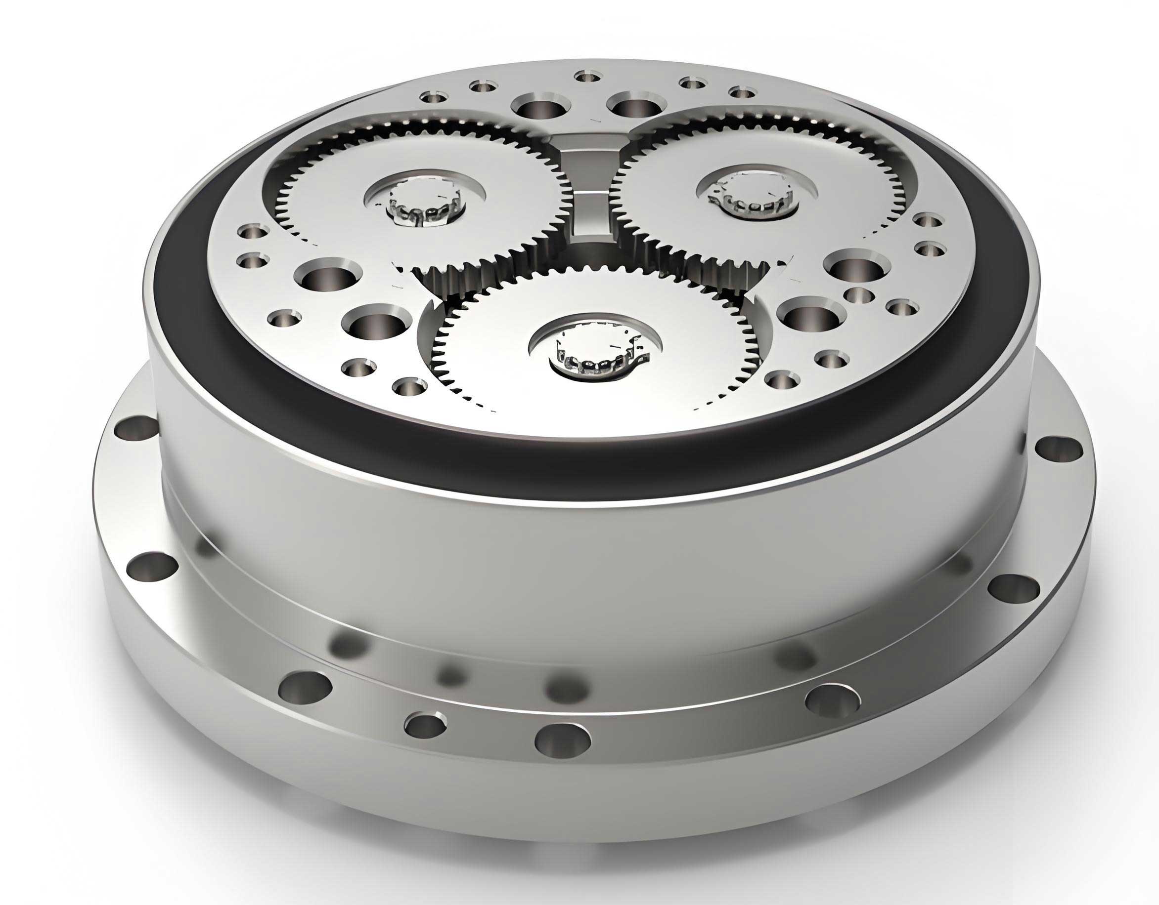
The rotary vector reducer is a closed differential gear train. Its operation can be divided into two primary reduction stages. The first stage is a standard planetary gear system. An input shaft, connected to a sun gear, drives three planetary gears housed within a rotating carrier (the crankshaft assembly). This planetary carrier does not directly output motion. Instead, the second stage, a cycloidal-pin gear mechanism, takes over. The crankshafts, which are eccentric, are integrated into the planetary carrier. Each crankshaft drives a cycloidal disc (or a pair of discs for balance), which meshes with a stationary ring of pin gears housed in the pin gear casing. The unique motion of the cycloidal disc, a combination of revolution and counter-rotation, is translated into a slow, uniform rotation of the output flange through a set of pins or rollers in the output mechanism.
The total reduction ratio (i) of the rotary vector reducer is the product of the ratios from both stages and is given by:
$$ i = (1 + \frac{Z_p}{Z_s}) \times (Z_{pin}) $$
Where:
- $Z_s$ is the number of teeth on the sun gear,
- $Z_p$ is the number of teeth on each planet gear,
- $Z_{pin}$ is the number of pin gears in the stationary ring.
This compound design allows the rotary vector reducer to achieve single-stage ratios typically ranging from 30:1 to over 200:1, making it ideal for direct drive applications in robotic joints.
2. Three-Dimensional Parametric Modeling
Accurate geometric modeling is the precursor to any meaningful simulation. While components like the sun gear, planet gears, and housing can be modeled using standard CAD features, the cycloidal disc requires a parametric approach due to its complex tooth profile. The tooth flank of a cycloidal disc is generated based on the theory of hypotrochoids or epitrochoids, depending on the design. The parametric equations for a standard cycloidal profile (considering pin diameter and equidistant offset) are:
$$ x = (R_p – E \cdot \cos(Z_{pin} \cdot \theta)) \cdot \cos(\theta) + (E \cdot \sin(Z_{pin} \cdot \theta)) \cdot \sin(\theta) $$
$$ y = (R_p – E \cdot \cos(Z_{pin} \cdot \theta)) \cdot \sin(\theta) – (E \cdot \sin(Z_{pin} \cdot \theta)) \cdot \cos(\theta) $$
Where:
- $R_p$ is the radius of the pin gear center circle,
- $E$ is the eccentricity of the crankshaft,
- $Z_{pin}$ is the number of pin gears,
- $\theta$ is the generating angle parameter (from $0$ to $2\pi$).
Using CAD software’s expression/equation tool, these formulas were implemented to generate a precise sketch of the cycloidal tooth profile. This sketch was then extruded to create a solid body. Subsequent features, such as the holes for the crankshaft bearings and the output pins, were added using Boolean operations. The final fully constrained assembly of the rotary vector reducer model ensures accurate mating conditions for the subsequent finite element analysis.
3. Transient Dynamics Analysis for Contact Stress Evaluation
Transient dynamic analysis is crucial for understanding the time-varying stresses within the rotary vector reducer during operation. This analysis focuses on the two primary meshing interfaces: the sun-planet gear pair (first stage) and the cycloidal disc-pin gear pair (second stage).
3.1 Sun Gear and Planet Gear Meshing Analysis
The first stage operates at higher rotational speeds. For this analysis, a sub-assembly containing the sun gear and one planet gear was extracted. The material properties assigned are critical for accurate stress computation.
| Component | Material | Density (kg/m³) | Young’s Modulus (GPa) | Poisson’s Ratio |
|---|---|---|---|---|
| Sun Gear | 20CrMnTi | 7.86e3 | 212 | 0.289 |
| Planet Gear | 40Cr | 7.87e3 | 206 | 0.277 |
A high-quality hex-dominant mesh was generated, with significant refinement applied to the tooth surfaces involved in contact. A frictional contact pair was defined between the gear teeth, with the sun gear as the contact body and the planet gear as the target body (a coefficient of friction of 0.15 was used). Kinematic conditions were applied: a rotary velocity of 140.25 rad/s was applied to the sun gear’s axis, and a resistive torque of 4.8775 N·m was applied to the planet gear’s axis, simulating the load from the subsequent stage. The simulation solved for several cycles of mesh engagement.
Results: The maximum contact stress was found to be 91.53 MPa, located precisely at the point of mesh engagement between the sun and planet gear teeth. Stress at the tooth root was secondary, indicating minor bending deflection well within the elastic limit and material endurance strength. No significant stress concentration was observed on the tooth flanks, confirming that the first-stage gearing of the rotary vector reducer operates safely under the applied load.
3.2 Cycloidal Disc and Pin Gear Meshing Analysis
The second stage handles significantly higher torque at lower speeds. A sub-model containing one cycloidal disc meshing with several stationary pin gears was analyzed. The pin gear casing was treated as a rigid support.
| Component | Material | Density (kg/m³) | Young’s Modulus (GPa) | Poisson’s Ratio |
|---|---|---|---|---|
| Cycloidal Disc | G20CrMo | 7.80e3 | 208 | 0.292 |
| Pin Gear | GCr15 | 7.80e3 | 219 | 0.300 |
The mesh was controlled with fine sizing on the cycloidal disc teeth and the pin gear cylinders. Contact pairs were established between the flank of the cycloidal disc (contact body) and the cylindrical surface of each pin gear (target body), with a friction coefficient of 0.13. The pin gears were fully constrained. A torque of 774 N·m, representative of the output load, was applied to the central bore of the cycloidal disc where it connects to the output mechanism.
Results: The analysis revealed a complex stress field. The maximum contact stress reached 420.44 MPa. Interestingly, this peak stress did not occur directly at the theoretical meshing point with a pin but was concentrated at the edge of the crankshaft bearing hole on the side of the cycloidal disc currently engaged in carrying the load. This indicates that the load path through the disc creates a significant bending moment around the bearing hole. Stress was also distributed around other holes (e.g., output pin holes). While this stress is within the yield strength of case-hardened G20CrMo, it highlights a critical area for design optimization in the rotary vector reducer, suggesting potential reinforcement or fillet optimization around these holes.
4. Modal Analysis for Dynamic Characteristic Assessment
To ensure operational stability and avoid resonant vibrations, a modal analysis of the complete rotary vector reducer assembly and a separate analysis of the cycloidal disc were conducted. This determines the natural frequencies and corresponding mode shapes of the system.
4.1 Full Assembly Constrained Modal Analysis
The entire rotary vector reducer assembly was imported and meshed. Realistic boundary conditions were applied to simulate its mounted state: the base of the pin gear casing was fixed, and the input sun gear shaft was allowed to rotate only about its axis. All component contacts (gear meshes, bearings, bolts) were simplified as bonded connections for this linear modal analysis. The material properties for key components are summarized below:
| Component | Material | Density (kg/m³) | Young’s Modulus (GPa) | Poisson’s Ratio |
|---|---|---|---|---|
| Cycloidal Disc | G20CrMo | 7.80e3 | 208 | 0.292 |
| Pin Gear | GCr15 | 7.80e3 | 219 | 0.300 |
| Sun Gear | 20CrMnTi | 7.86e3 | 212 | 0.289 |
| Planet Gear | 40Cr | 7.87e3 | 206 | 0.277 |
| Housing/Output Flange | Structural Steel / 45 Steel | 7.85e3 / 7.89e3 | 200 / 209 | 0.30 / 0.269 |
The analysis solved for the first 16 modes. The first six non-zero natural frequencies (modes 1-6) of the constrained assembly are listed below. The corresponding mode shapes primarily involved complex coupled bending and twisting of the housing, planet carrier, and output flange assembly.
| Mode | 1 | 2 | 3 | 4 | 5 | 6 |
|---|---|---|---|---|---|---|
| Frequency (Hz) | 2291 | 2372 | 2382 | 2913 | 2919 | 2989 |
4.2 Cycloidal Disc Component Modal Analysis
A separate modal analysis was performed on the cycloidal disc alone, with constraints applied only to its central bore (allowing rotation). This isolates its flexible body modes. The first 16 natural frequencies were extracted, with the first six flexible modes shown conceptually below (the first mode is a near-rigid body mode at ~0 Hz).
| Mode | 1 (≈0) | 2 | 3 | 4 | 5 | 6 |
|---|---|---|---|---|---|---|
| Frequency (Hz) | ~0 | 1553.7 | 1553.7 | 1717.8 | 2202.0 | 2202.1 |
Resonance Avoidance Check: A critical step is to compare these natural frequencies with potential excitation frequencies from the rotary vector reducer‘s operation. The primary excitation comes from gear meshing. The meshing frequency ($f_m$) for a gear pair is calculated by:
$$ f_m = \frac{n \cdot Z}{60} $$
Where $n$ is the rotational speed in RPM and $Z$ is the number of teeth. For the first-stage sun gear operating at 1815 RPM with, for example, 20 teeth, the meshing frequency is $f_{m1} = (1815 * 20) / 60 = 605$ Hz. For the second-stage cycloidal disc, operating at a reduced speed of ~15 RPM and meshing with, for example, 40 pin gears, the meshing frequency is $f_{m2} = (15 * 40) / 60 = 10$ Hz.
The analysis clearly shows that the natural frequencies of the full rotary vector reducer assembly (starting above 2200 Hz) and the cycloidal disc component (flexible modes above 1500 Hz) are significantly higher than the primary meshing excitation frequencies (605 Hz and 10 Hz). This substantial separation margin indicates a low risk of resonance during normal operation, contributing to the smooth and reliable performance for which the rotary vector reducer is known.
5. Discussion and Design Implications
The comprehensive FEA performed provides valuable, actionable insights for the design and optimization of the rotary vector reducer:
- Contact Stress Management: The sun-planet gear pair shows a safe and well-distributed contact stress pattern, validating the standard gear design for the first stage. The cycloidal disc analysis, however, reveals that the highest stress is not at the tooth contact but is a structural stress concentrated at the crankshaft bearing hole. This is a critical finding. Future design iterations of the rotary vector reducer should focus on optimizing the geometry around this hole—increasing local thickness, applying larger fillet radii, or using advanced surface treatments—to reduce this stress concentration and improve fatigue life.
- Dynamic Robustness: The modal analysis confirms the inherent stiffness of the rotary vector reducer design. The high natural frequencies relative to operational excitation frequencies ensure a wide operational envelope free from resonance. This is a key advantage in robotic applications where varying speeds and loads are common. Designers must maintain this stiffness during any weight-reduction or compactness optimization efforts.
- Material Selection Validation: The stress levels observed (91.53 MPa and 420.44 MPa) are well within the allowable contact stress limits for the selected high-strength, case-hardened alloys (20CrMnTi, G20CrMo, GCr15). This validates the standard material choices for the rotary vector reducer.
- Analysis Methodology: This work demonstrates an effective workflow combining parametric CAD modeling, transient dynamic contact analysis, and modal analysis using commercial FEA software. This workflow is essential for virtually prototyping and optimizing complex gear systems like the rotary vector reducer before physical manufacturing, reducing development time and cost.
6. Conclusion
This article presented a detailed finite element-based investigation into the transmission performance of a rotary vector reducer. Through transient dynamics analysis, the contact stress behavior of the two critical meshing stages was elucidated. The first-stage planetary gear mesh exhibited a maximum stress of 91.53 MPa at the contact point, confirming safe operation. The second-stage cycloidal-pin gear mesh presented a more complex stress field, with a peak stress of 420.44 MPa localized at the edge of the loaded crankshaft bearing hole in the cycloidal disc, identifying a primary area for potential design enhancement.
Furthermore, a constrained modal analysis of the full assembly and the cycloidal disc component revealed natural frequencies starting at 2291 Hz and 1553 Hz, respectively. These frequencies possess a substantial margin compared to the calculated gear meshing excitation frequencies (605 Hz and 10 Hz), ensuring that the rotary vector reducer is immune to resonant vibrations during typical operation. The insights gained from this comprehensive analysis—particularly regarding stress concentrations and dynamic stiffness—provide a solid foundation for the ongoing design refinement, lightweight optimization, and reliability assurance of the high-performance rotary vector reducer, solidifying its role as a critical component in advanced precision machinery.