
The analysis of gear dynamics and contact mechanics is a cornerstone of modern mechanical design. Among various gear types, spur gears remain fundamental components in power transmission systems due to their simplicity and efficiency in parallel shaft applications. However, conventional symmetric spur gears, where both flanks share the same pressure angle, are not always optimal for applications involving unidirectional power flow. This has led to significant interest in asymmetric spur gear designs, where the driving (or working) flank and the coast (or non-working) flank possess different pressure angles. This asymmetry can be strategically leveraged to enhance performance metrics such as bending strength, contact fatigue life, and noise characteristics on the critical working flank, while the non-working flank is designed primarily to avoid interference. This article presents a first-person account of developing and validating a comprehensive analytical model for evaluating the meshing and vibration characteristics of asymmetric spur gears, with particular emphasis on incorporating the effects of tooth modifications, which are crucial for real-world applications.
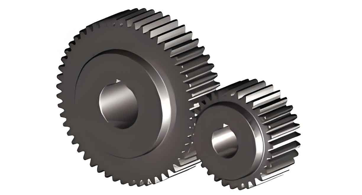
The core challenge in modeling asymmetric spur gears lies in accurately predicting their time-varying mesh stiffness and nonlinear contact behavior. While finite element analysis (FEA) offers a powerful tool, it is computationally intensive, especially for dynamic simulations and parametric studies. Therefore, the development of efficient yet accurate analytical or semi-analytical models is highly desirable. The model discussed here is built upon the foundational principles of the potential energy method and the slice theory, extended to address the unique geometry of asymmetric teeth and common manufacturing adjustments like tip and lead crowning.
In standard symmetric spur gears, the mesh stiffness varies periodically as the number of tooth pairs in contact changes between one and two (or more, for high-contact-ratio designs). This stiffness fluctuation is a primary source of parametric excitation, leading to vibration and noise. For asymmetric spur gears, this behavior is further complicated by the altered tooth geometry. A larger pressure angle on the working flank, for instance, increases the tooth thickness at the root and reduces the contact ratio, both of which significantly impact the stiffness function and stress distribution.
Analytical Model for Meshing Characteristics
The modeling approach treats the gear pair as a series of independent slices along the face width to account for lead (crowning) modifications. Each thin slice is modeled as a non-uniform cantilever beam. The total mesh stiffness for a slice is a combination of the bending, shear, and axial compressive stiffnesses of the two mating teeth, the variable contact (Hertzian) stiffness at the interface, and the contributions from the gear body (foundation stiffness).
The geometry of an asymmetric tooth is defined by two distinct pressure angles: $α_d$ for the driving flank and $α_c$ for the coast flank. This asymmetry directly influences the tooth thickness at any radius. The half-tooth thicknesses on the driving side ($s_d$) and coast side ($s_c$) are calculated based on the respective involute equations and base circle radii. For a slice of width $ΔL = L/N$, where $L$ is the total face width and $N$ is the number of slices, the area $A_i$ and moment of inertia $I_i$ for a tooth section at a distance $x$ from the root are given by:
$$ A_i(x) = (s_d(x) + s_c(x)) \cdot ΔL $$
$$ I_i(x) = \frac{(s_d(x) + s_c(x))^3 \cdot ΔL}{12} $$
The stiffness components for the $i$-th tooth pair in mesh are then calculated using strain energy principles. The bending stiffness $k_b$, shear stiffness $k_s$, and axial stiffness $k_a$ for a pinion ($p$) or gear ($g$) tooth are derived from integrals along the tooth profile from the root to the contact point:
$$ \frac{1}{k_{b}} = \int_{0}^{d} \frac{[M(x)]^2}{E I(x)} dx, \quad \frac{1}{k_{s}} = \int_{0}^{d} \frac{1.2 [V(x)]^2}{G A(x)} dx, \quad \frac{1}{k_{a}} = \int_{0}^{d} \frac{[F(x)]^2}{E A(x)} dx $$
where $E$ is Young’s modulus, $G$ is the shear modulus, $d$ is the effective cantilever length, and $M(x)$, $V(x)$, $F(x)$ are the moment, shear force, and axial force at section $x$, respectively. The contact stiffness $k_h$ for the slice, representing the nonlinear Hertzian contact, is approximated by:
$$ k_h = \frac{π E ΔL}{4(1-ν^2)} \quad \text{or alternatively,} \quad k_h^i = E \cdot ΔL \cdot \left( \frac{F \cdot lsr^i}{ΔL} \right)^{0.1} / 1.275^{0.9} $$
where $ν$ is Poisson’s ratio, $F$ is the total normal load, and $lsr^i$ is the load-sharing ratio for the $i$-th pair. The total mesh stiffness for the $i$-th pair in a slice is then assembled from these components in series:
$$ \frac{1}{k_{pair}^i} = \frac{1}{k_{bp}^i + k_{sp}^i + k_{ap}^i} + \frac{1}{k_{bg}^i + k_{sg}^i + k_{ag}^i} + \frac{1}{k_h^i} $$
To account for the flexibility of the gear body beyond the tooth, a foundation stiffness correction factor $λ$ is applied. The comprehensive mesh stiffness $K_{slice}^n$ for the $n$-th slice, considering two potential tooth pairs in contact ($i$ and $j$), is the parallel sum of the pair stiffnesses, adjusted for foundation effects and any lead crowning error $E_c^n$:
$$ \frac{1}{K_{slice}^n} = \frac{1}{λ_p k_{fp}} + \frac{1}{λ_g k_{fg}} + \frac{1}{k_{pair}^i + k_{pair}^j} $$
The total effective mesh stiffness $K_{total}$ for the entire gear pair at a given angular position is calculated by summing the contributions from all loaded slices, considering the load distribution influenced by lead crowning:
$$ K_{total} = \frac{F + \sum_{n=1}^{N} K_{slice}^n E_c^n }{\sum_{n=1}^{N} δ_n} \quad \text{where } δ_n \text{ is the deflection of slice n}. $$
The static transmission error (STE), a key excitation source, is computed from the mesh stiffness and the applied load, incorporating tooth profile modifications (like tip relief) as geometric deviations $E_i$:
$$ STE = \frac{F + k_{pair}^1 E_1 + k_{pair}^2 E_2}{k_{pair}^1 + k_{pair}^2} $$
Contact stress is evaluated using the classical Hertzian formula, with the load distributed among slices and tooth pairs according to the calculated load-sharing ratios $lsr_n^i$:
$$ σ_H^n = \sqrt{ \frac{F \cdot lsr_n^i / ΔL}{π (1-ν^2)} \cdot \frac{E}{ \frac{1}{ρ_p} + \frac{1}{ρ_g} } } $$
where $ρ_p$ and $ρ_g$ are the radii of curvature at the contact point on the pinion and gear, respectively.
Model Validation and Parametric Studies on Meshing
To validate the proposed analytical model for asymmetric spur gears, comparisons were made against detailed 3D nonlinear finite element analyses. A representative gear pair with 19 teeth each, module of 2.87 mm, and face width of 16 mm was analyzed under a torque of 52.25 Nm. The model’s accuracy and computational efficiency were assessed.
| Pressure Angle $α_d$ (°) | Analytical Mesh Stiffness Max (N/m) | FEA Mesh Stiffness Max (N/m) | Error (%) | Analytical Contact Stress Max (MPa) | FEA Contact Stress Max (MPa) |
|---|---|---|---|---|---|
| 20 | 3.23e8 | 3.29e8 | 1.8 | 1080 | 1110 |
| 22.69 | 3.36e8 | 3.40e8 | 1.2 | 980 | 1010 |
| 28 | 3.62e8 | 3.64e8 | 0.6 | 890 | 910 |
The results demonstrated excellent agreement. As seen in Table 1, the error in peak mesh stiffness was within 2%, and contact stress predictions were similarly accurate. Crucially, the analytical model completed the stiffness calculation for a full mesh cycle in approximately 30 seconds, compared to several hours for the equivalent FEA simulation, marking a dramatic improvement in computational efficiency for asymmetric spur gears.
The impact of the working pressure angle $α_d$ was systematically studied. Increasing $α_d$ from 20° to 28° led to a stiffer tooth due to a thicker root section, increasing the maximum mesh stiffness by about 12%. However, this also reduced the transverse contact ratio, extending the duration of the single-tooth-contact region. Consequently, the maximum contact stress decreased significantly (by about 18%), as the load was shared over a smaller effective curvature radius but was borne by a single tooth for a longer period, with the geometric strengthening effect dominating.
| Modification Type | Key Parameter | Effect on Mesh Stiffness Profile | Primary Design Goal |
|---|---|---|---|
| None | – | Pronounced discontinuity at single/double tooth contact transitions. | Baseline reference. |
| Tip Relief | Amount: $C_a$, Length: $L_a$ | Smoothes the stiffness drop at the start and end of contact, reducing discontinuity. | Mitigate meshing impact, reduce vibration excitation. |
| Lead Crowning | Crown Amount: $C_β$ | Reduces overall stiffness magnitude; promotes load distribution towards the center of the face width. | Compensate for misalignment and shaft deflection, improve contact pattern. |
| Combined (Tip & Lead) | $C_a$, $L_a$, $C_β$ | Combination of both effects: smoother transitions and reduced overall stiffness. | Optimize for both dynamic excitation and misalignment tolerance. |
The effects of tooth modifications, summarized in Table 2, are critical. Tip relief, a common profile modification, effectively reduces the stiffness discontinuity at the points of tooth engagement and disengagement, thereby lowering dynamic forces. Lead crowning, a profile modification along the face width, intentionally reduces edge loading by allowing slight deflections, which results in a lower effective mesh stiffness as only the central portion of the tooth carries the full load. The analytical slice model successfully captures these nuanced effects for asymmetric spur gears.
Dynamic Modeling and Vibration Response
Building upon the precise meshing characteristics model, a coupled lateral-torsional-axial dynamic model of the asymmetric spur gear pair is established. The system is modeled with 12 degrees of freedom (DOF), accounting for the translational motions ($x, y, z$) and rotational motions ($θ_x, θ_y, θ_z$) of both the pinion and gear shafts, considered as rigid bodies connected by the time-varying mesh stiffness $k_m(t)$ and damping $c_m$ calculated from the previous section.
The equations of motion are derived using Lagrange’s equation or Newton’s second law. The generalized coordinate vector is:
$$ \mathbf{X} = [x_p, y_p, z_p, θ_{xp}, θ_{yp}, θ_{zp}, x_g, y_g, z_g, θ_{xg}, θ_{yg}, θ_{zg}]^T $$
The dynamic transmission error (DTE) along the line of action is the primary response variable, defined as the relative displacement between the two gears projected onto the mesh direction:
$$ \delta(t) = (x_p – x_g)\sinα_d + (y_p – y_g)\cosα_d + r_{bp}θ_{zp} + r_{bg}θ_{zg} – e(t) $$
Here, $r_b$ is the base radius and $e(t)$ is the static transmission error (STE) from the meshing model, serving as a kinematic excitation. The governing equation for the torsional-lateral coupled system can be expressed in matrix form:
$$ \mathbf{M}\ddot{\mathbf{X}} + (\mathbf{C} + \mathbf{G})\dot{\mathbf{X}} + \mathbf{K}(t)\mathbf{X} = \mathbf{F}(t) $$
where $\mathbf{M}$ is the mass matrix, $\mathbf{C}$ is the damping matrix (often proportional), $\mathbf{G}$ is the gyroscopic matrix, $\mathbf{K}(t)$ is the time-varying stiffness matrix which contains the periodic mesh stiffness $k_m(t)$, and $\mathbf{F}(t)$ is the force vector including the transmitted torque and excitation from STE. The periodic variation of $k_m(t)$ makes this a parametrically excited system.
The dynamic response is analyzed in the frequency domain. The system’s natural frequencies are first evaluated using the average mesh stiffness $\bar{k_m}$. For the example asymmetric spur gear pair, the first major natural frequency associated with the torsional-lateral mode decreases slightly with increasing working pressure angle due to the increased system mass (from thicker teeth) outweighing the stiffness increase in this particular mode. As $α_d$ increases from 20° to 28°, $f_{n1}$ drops from approximately 2134 Hz to 2091 Hz.
The forced frequency response reveals significant insights. The primary resonance peak occurs when the mesh frequency $f_m$ (or its harmonics) coincides with a system natural frequency. Furthermore, due to the parametric excitation from $k_m(t)$, prominent super-harmonic and sub-harmonic resonance peaks are observed at fractions of the primary resonance frequency ($f_{n1}/2$, $f_{n1}/3$, etc.). The key finding is that as the asymmetry increases (higher $α_d$), the dynamic response amplitude generally increases. This is attributed to the reduction in contact ratio, which amplifies the fluctuation between the high stiffness of double-tooth contact and the lower stiffness of single-tooth contact. This larger stiffness variation creates a stronger parametric excitation source, driving higher vibration levels despite the reduction in contact stress.
| Performance Metric | Trend with Increasing $α_d$ | Underlying Physical Reason | Design Implication |
|---|---|---|---|
| Bending Strength | Increases | Thicker tooth root section. | Beneficial for high-torque applications. |
| Contact Stress ($σ_H$) | Decreases | Increased effective curvature radius (in single contact) and load-bearing capacity. | Improves pitting resistance. |
| Mesh Stiffness | Increases | Thicker, more robust tooth geometry. | Higher system natural frequencies (torsional). |
| Contact Ratio | Decreases | Steeper pressure angle reduces path of contact. | May increase load per tooth. |
| Dynamic Vibration Amplitude | Increases | Larger stiffness variation due to lower contact ratio. | Potentially higher noise; needs balancing with modifications. |
| Primary Natural Frequency | Slightly Decreases | Increased tooth mass can outweigh stiffness gain for certain modes. | Requires careful dynamic system analysis. |
Conclusions
This detailed exposition has presented a robust and efficient analytical framework for the comprehensive analysis of asymmetric spur gear pairs. The model successfully integrates key mechanical aspects: the asymmetric tooth geometry, nonlinear Hertzian contact, extended tooth contact conditions, gear body flexibility, and realistic tooth modifications (tip relief and lead crowning). Validated against finite element analysis, the model demonstrates high accuracy in predicting time-varying mesh stiffness and contact stress for asymmetric spur gears while offering computational speeds orders of magnitude faster, making it ideal for design optimization and probabilistic analysis.
The parametric studies yield clear design guidelines, synthesized in Table 3. Increasing the working pressure angle enhances static strength characteristics—reducing contact stress and increasing bending capacity—which is highly advantageous for durability. However, this benefit for asymmetric spur gears comes at the cost of dynamic performance: a lower contact ratio amplifies mesh stiffness variations, leading to increased parametric excitation and higher vibration amplitudes. Furthermore, the system’s fundamental natural frequency may experience a slight downward shift. Therefore, the design of high-performance asymmetric spur gears necessitates a multi-objective compromise. The analytical model proves that tooth modifications, particularly optimized tip relief, are indispensable in mitigating the dynamic drawbacks of asymmetry. By carefully tailoring the pressure angle asymmetry and modification parameters, designers can achieve an optimal balance between the superior load-carrying capacity of asymmetric spur gears and acceptable vibration and noise levels, enabling their effective use in advanced, high-power-density transmission systems.