
In the field of industrial robotics, precision motion control is paramount, and the rotary vector reducer plays a critical role as a high-precision transmission component in robot joints. The rotary vector reducer is renowned for its compact structure, high reduction ratio, and superior rigidity, making it indispensable in applications requiring accurate and reliable power transmission. The transmission performance of the rotary vector reducer is largely dominated by its second-stage cycloidal pin wheel drive, which directly influences the overall output accuracy due to its connection to the output shaft. Therefore, understanding the meshing behavior, including contact stress distribution, number of simultaneously engaged teeth, and the effects of modifications and initial gaps, is essential for optimizing the design and performance of rotary vector reducers. This study employs a combined approach of theoretical analysis, finite element simulation using ANSYS, and numerical computation with MATLAB to delve into the meshing characteristics of the cycloidal drive in a rotary vector reducer, with a focus on real-world loading conditions.
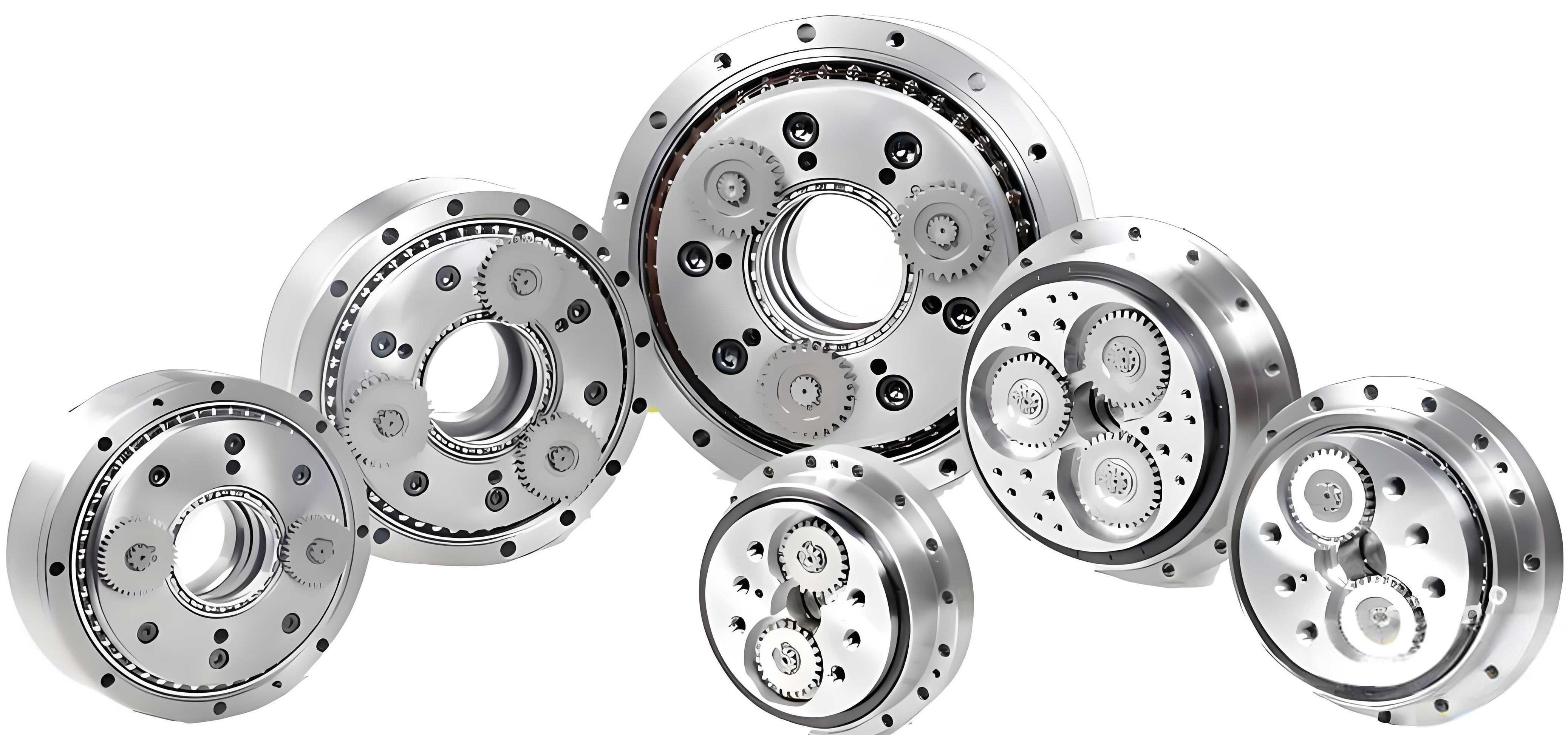
The cycloidal pin wheel transmission in a rotary vector reducer typically involves multiple teeth in simultaneous contact, which enhances load capacity and reduces transmission error. However, in practice, manufacturing tolerances, assembly errors, and the need for effective lubrication necessitate modifications to the standard cycloidal tooth profile. Common modification methods include equidistant modification, shift modification, and rotational angle modification. These modifications alter the tooth geometry, thereby affecting the initial clearance between the cycloidal wheel and the pin teeth during meshing. The general equation for the modified cycloidal tooth profile can be expressed as follows, incorporating these adjustments to compensate for operational imperatives:
$$
\begin{aligned}
x &= \left( r_p + \Delta r_p \right) \sin(\phi_i) – \left( a + \Delta a \right) \sin(z_c \phi_i) – \delta \sin(\phi_i – \theta) \\
y &= \left( r_p + \Delta r_p \right) \cos(\phi_i) – \left( a + \Delta a \right) \cos(z_c \phi_i) – \delta \cos(\phi_i – \theta)
\end{aligned}
$$
where \( r_p \) is the radius of the pin tooth center circle (in mm), \( \Delta r_p \) is the equidistant modification amount, \( a \) is the eccentricity (in mm), \( \Delta a \) is the shift modification amount, \( z_c \) is the number of pin teeth, \( \phi_i \) is the angle of the pin wheel relative to the swing arm, \( \delta \) is related to the tooth profile, and \( \theta \) is the rotational modification angle. The parameter \( z_c \) is defined as \( z_c = z_b / z_p \), with \( z_b \) being the number of cycloidal wheel teeth. These modifications ensure that the rotary vector reducer can accommodate slight misalignments and reduce wear, but they also introduce variations in the initial clearance between mating teeth.
The initial clearance along the normal direction for the i-th tooth pair, after modifications, is given by:
$$
\Delta_i = \Delta r_p \left( 1 – \cos(\psi_i) \right) + \Delta a \left( 1 – K_1 \cos(\psi_i) \right) – a K_1 \theta \sin(\psi_i)
$$
where \( \psi_i \) is the angle of the i-th pin tooth relative to the initial meshing pin tooth (in degrees), and \( K_1 \) is the shortening coefficient, defined as \( K_1 = a z_c / r_p \). By setting the derivative \( d\Delta_i / d\psi_i = 0 \), we can find the extremum points of the initial clearance distribution. Solving yields:
$$
\psi_{m1} = \arcsin\left( \frac{a K_1 \theta}{\Delta r_p + K_1 \Delta a} \right), \quad \psi_{m2} = \pi – \psi_{m1}
$$
The distribution curve of \( \Delta_i \) versus \( \psi_i \) typically shows two intersection points, \( \psi_{m1} \) and \( \psi_{m2} \), which define the range where teeth may engage based on deformation and clearance. This theoretical framework is crucial for predicting the number of simultaneously meshing teeth in a rotary vector reducer under load.
To analyze the meshing characteristics thoroughly, a static simulation study was conducted using ANSYS on an RV-20E rotary vector reducer model. The model was simplified by omitting minor features like fillets and bolt holes to focus on the essential meshing behavior of the cycloidal drive. The key parameters of the rotary vector reducer are summarized in the table below, providing a foundation for the simulation inputs.
| Parameter Name | Value | Parameter Name | Value |
|---|---|---|---|
| Pin tooth center circle diameter (mm) | 104.3 | Pressure angle (degrees) | 20 |
| Pin tooth diameter (mm) | 4 | Equidistant modification amount (mm) | -0.01 |
| Eccentricity (mm) | 0.9 | Shift modification amount (mm) | -0.012 |
| Number of cycloidal wheel teeth | 39 | Cycloidal wheel width (mm) | 8 |
| Input sun gear teeth number | 12 | First-stage transmission modification coefficient sum | 0.35526 |
| Planet gear teeth number | 24 | First-stage transmission center distance (mm) | 27.5 |
| Module (mm) | 1.5 |
The material properties assigned in the simulation are critical for accurate stress analysis. The following table details the materials used for various components of the rotary vector reducer, ensuring realistic deformation responses under load.
| Component | Material | Density (kg/mm³) | Elastic Modulus (MPa) | Poisson’s Ratio |
|---|---|---|---|---|
| Input shaft | 15CrMo | 7.88×10⁻⁶ | 2.12×10⁵ | 0.284 |
| Planet gear | 38CrMoAl | 7.85×10⁻⁶ | 2.11×10⁵ | 0.277 |
| Crankshaft | 20CrMo | 7.82×10⁻⁶ | 2.11×10⁵ | 0.292 |
| Cycloidal wheel | GCr15 | 7.83×10⁻⁶ | 2.19×10⁵ | 0.3 |
| Pin tooth | GCr15 | 7.83×10⁻⁶ | 2.19×10⁵ | 0.3 |
| Other parts | 45 steel | 7.89×10⁻⁶ | 2.09×10⁵ | 0.269 |
The ANSYS simulation involved applying rotational loads at the input to simulate torque transmission through the rotary vector reducer. Loads of 80 N·m, 110 N·m, 140 N·m, 170 N·m, 200 N·m, and 230 N·m were applied to study the effect of varying torque on meshing behavior. The contact stress distributions were extracted, and the number of simultaneously engaged teeth was determined for each load case. The results consistently showed that five teeth on a single cycloidal wheel were in contact under all tested loads, indicating that the meshing pattern stabilizes above 80 N·m in this rotary vector reducer configuration. With two cycloidal wheels phased 180 degrees apart, the total number of engaged teeth in the system is ten, which contributes to the high load capacity and smooth operation of the rotary vector reducer.
The contact stress trends over time revealed interesting dynamics. During the initial 0 to 0.5 seconds, the contact stress magnitude was similar across different loads, quickly reaching a steady state. From 0.5 to 7 seconds, lower loads resulted in higher contact stress, while higher loads exhibited more stable stress levels. In the final 7 to 8 seconds, contact stress decreased for lower loads and increased rapidly, highlighting transient effects in the rotary vector reducer meshing. For individual cycloidal teeth, the contact stress typically increased sharply to a maximum and then gradually decreased, reflecting the loading and unloading sequence as teeth engage and disengage. Additionally, along the tooth width direction (from the outer to inner sides of the cycloidal wheel pair), the contact stress showed a gradual increasing trend, which is important for understanding wear and fatigue in rotary vector reducer components.
The theoretical determination of simultaneously meshing teeth in a rotary vector reducer is based on the principle that teeth enter meshing when the total deformation along the common normal direction at their contact points exceeds the initial clearance at those positions. The total deformation \( \delta_i \) for the i-th tooth pair is given by:
$$
\delta_i = l_i \beta \quad (i = 1, 2, \ldots, z_b/2)
$$
where \( l_i \) is the distance from the cycloidal wheel center \( O_c \) to the common normal at the i-th pin tooth meshing point, and \( \beta \) is the rotation angle of the cycloidal wheel due to deformation under load. The distance \( l_i \) can be calculated as:
$$
l_i = r_c’ \cos(\alpha_i)
$$
Here, \( r_c’ \) is the pitch circle radius of the cycloidal wheel, and \( \alpha_i \) is the angle between the common normal and the line \( O_cO_p \). The deformation components include contact deformation of the cycloidal wheel and bending deformation of the pin teeth, though the latter is often negligible. For the most heavily loaded tooth pair near the direction of force transmission, the contact deformation \( w_{\text{max}} \) and pin bending deformation \( f_{\text{max}} \) are:
$$
w_{\text{max}} = \frac{2(1 – \nu^2)}{\pi E B} \left( \frac{2}{3} + \ln \frac{4 \rho_c}{b} \right) F_{\text{max}}, \quad f_{\text{max}} = \frac{F_{\text{max}} L^3}{3E I}
$$
where \( \nu \) is Poisson’s ratio, \( E \) is the elastic modulus, \( B \) is the cycloidal wheel width, \( \rho_c \) is the curvature radius of the cycloidal tooth profile at the meshing point, \( L \) is the pin tooth length, and \( I \) is the moment of inertia. The maximum contact load \( F_{\text{max}} \) for the most loaded tooth is related to the output torque \( T \) of the rotary vector reducer by:
$$
F_{\text{max}} = \frac{T_c}{r_c’ \sum_{i=1}^{n} \cos(\alpha_i)}, \quad T_c = 0.55T
$$
assuming manufacturing variations where \( T_c \) is the torque on a single cycloidal wheel. By comparing the deformation \( \delta_i \) distribution with the initial clearance \( \Delta_i \) distribution, the angles \( \psi_{m1} \) and \( \psi_{m2} \) define the range of teeth that actively participate in meshing, thus determining the number of simultaneously engaged teeth in the rotary vector reducer.
To complement the simulation, a numerical analysis was performed using MATLAB to compute the maximum contact load and number of contact teeth under different torques. The algorithm involved iterating over tooth pairs, calculating deformations and clearances, and checking engagement conditions based on the theoretical model. The results are summarized in the table below, confirming the simulation findings and providing quantitative load data.
| Torque (N·m) | Maximum Contact Load (N) | Number of Contact Teeth Pairs |
|---|---|---|
| 80 | 407.39 | 5 |
| 110 | 455.11 | 5 |
| 140 | 498.10 | 5 |
| 170 | 543.43 | 5 |
| 200 | 603.19 | 5 |
| 230 | 650.40 | 5 |
The MATLAB results align closely with the ANSYS simulations, both indicating five simultaneously meshing teeth per cycloidal wheel across the torque range. This consistency validates the theoretical approach and underscores the reliability of using combined simulation and numerical methods for analyzing rotary vector reducer meshing characteristics. The maximum contact load increases with torque, as expected, which has implications for durability and design margins in rotary vector reducer applications.
In conclusion, this study provides a detailed investigation into the meshing behavior of the cycloidal pin wheel drive in a rotary vector reducer. Through theoretical derivations, finite element simulations, and numerical computations, several key insights emerge. First, the number of simultaneously engaged teeth stabilizes at five per cycloidal wheel for loads above 80 N·m in the analyzed rotary vector reducer model, contributing to its robust performance. Second, contact stress dynamics vary with load magnitude and time, showing complex transient behaviors that must be considered in design. Third, tooth width direction stress gradients highlight potential areas for optimization to enhance fatigue life. The integration of ANSYS and MATLAB tools offers a comprehensive framework for evaluating rotary vector reducer transmission accuracy and load distribution. These findings serve as a valuable reference for further research on meshing characteristics, including effects of dynamic loads, thermal variations, and advanced materials in rotary vector reducers. Future work could explore real-time monitoring or adaptive control strategies to further improve the precision and reliability of rotary vector reducers in industrial robotics and other high-stakes applications.
The rotary vector reducer remains a cornerstone of precision motion systems, and understanding its intricate meshing mechanics is crucial for advancing robotic technologies. By leveraging simulation and analysis, engineers can optimize tooth profiles, minimize backlash, and ensure efficient power transmission, ultimately enhancing the performance and longevity of rotary vector reducers in diverse operational environments.