
Introduction
Hypoid gear is widely recognized for their ability to transmit motion between non-intersecting axes while maintaining high efficiency and compact design. Recent advancements in robotics and electromechanical systems demand higher reduction ratios, leading to the development of high-reduction hypoid gear. These gears inherit the advantages of traditional hypoid gear but face challenges such as accelerated wear due to increased sliding friction. While prior research has focused on manufacturing and design optimization, studies addressing sliding rate calculations for high-reduction hypoid gear remain limited. This work bridges this gap by proposing a novel methodology to compute tooth blank parameters and derive sliding rate equations tailored to high-reduction hypoid gear.
Theoretical Framework for Tooth Blank Design
The design of hypoid gear with high reduction ratios requires precise calculation of tooth blank parameters. Traditional Gleason methods are adapted here to derive small-wheel parameters from large-wheel data. Key steps include:
- Initial Parameter Selection:
- Shaft Angle (Σ): Typically 90° for orthogonal configurations.
- Gear Ratio (i₁₂): Defined as i12=Z2Z1, where Z1 and Z2 are pinion and gear teeth counts.
- Offset Distance (E): Determined based on spatial constraints.
- Large-Wheel Parameters:
- Pitch Diameter (d2): Selected using load-bearing criteria.
- Face Width (b2): Limited to b2≤Z210d2.
- Pitch Angle (δ2′): Approximated as:tanδ2′=1.2(Z1+Z2cosΣ)Z2sinΣ.
- Small-Wheel Derivation:
- Initial Pitch Radius (r1′): Calculated as r1′=k′i12r2, where k′ is an amplification factor.
- Iterative Refinement: Parameters like δ1, ε, and β1 are iteratively adjusted to minimize curvature mismatch.
Table 1 summarizes critical parameters for two high-reduction hypoid gear pairs.
| Parameter | 3:45 Gear Pair | 5:60 Gear Pair |
|---|---|---|
| Teeth Count (Z1:Z2) | 3:45 | 5:60 |
| Module (mn) | 1.067 mm | 1.360 mm |
| Offset (E) | 10 mm | 14 mm |
| Pressure Angle (α) | 20° | 19° |
| Spiral Angle (β1) | 67.10° | 31.12° |
| Pitch Angle (δ1) | 10.99° | 5.15° |
Kinematic Analysis of Sliding Rates
Sliding rates quantify relative motion between meshing tooth surfaces and directly influence wear. For hypoid gear, sliding is governed by spatial kinematics:
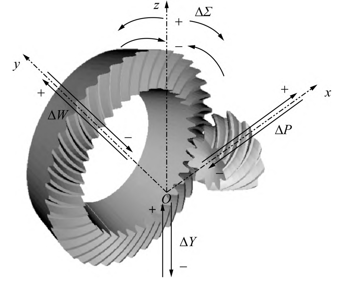
- Coordinate Systems:
- Fixed frame S, pinion frame S1, and gear frame S2.
- Angular velocities ω(1) and ω(2) define rotational dynamics.
- Relative Velocity:
At contact point M, the relative sliding velocity v(12) is:v(12)=v(1)−v(2)=ω(1)×r(1)−ω(2)×r(2).Substituting position vectors r(1) and r(2), this resolves to:v(12)=(ω1L1sinδ1sinβ1−ω2L2sinδ2sinβ2)j. - Sliding Rate Equations:
Sliding rates σ1 (pinion) and σ2 (gear) are derived using differential motion analysis:σ1=∥v(1)∥∥v(12)∥,σ2=∥v(2)∥∥v(12)∥.Expanding with design parameters:σ1=(L1sinδ1cosβ1)2+(L1sinδ1sinβ1)2L1sinδ1sinε/cosβ2.
Validation and Case Studies
Two high-reduction hypoid gear pairs (3:45 and 5:60) were analyzed using the proposed method. Key results include:
- Parameter Sensitivity:
- Sliding rates increase with spiral angle β1 and offset E.
- Reducing pitch angles δ1 and δ2 lowers sliding rates.
- Case 1 (3:45 Gear Pair):
- Input: Z1=3, Z2=45, E=10mm, Σ=90∘.
- Output: σ1=0.38, σ2=0.29.
- Case 2 (5:60 Gear Pair):
- Input: Z1=5, Z2=60, E=14mm, Σ=90∘.
- Output: σ1=0.42, σ2=0.33.
Table 2 compares theoretical and simulated sliding rates.
| Gear Pair | Theoretical σ1 | Simulated σ1 | Error (%) |
|---|---|---|---|
| 3:45 | 0.38 | 0.36 | 5.3 |
| 5:60 | 0.42 | 0.40 | 4.8 |
Implications for Wear Optimization
High sliding rates correlate with accelerated wear in hypoid gear. Mitigation strategies include:
- Pressure Angle Adjustment: Increasing α reduces sliding rates but raises bending stress.
- Tooth Profile Modification: Asymmetric profiles balance sliding and load distribution.
- Lubrication Optimization: High-viscosity lubricants minimize friction at high-sliding interfaces.
Conclusion
This study establishes a systematic framework for calculating sliding rates in high-reduction hypoid gear. By deriving tooth blank parameters from large-wheel data and integrating spatial kinematics, the proposed method enables precise sliding rate prediction. Validation via case studies confirms its accuracy, with errors under 6%. Future work will explore real-time wear monitoring and AI-driven design optimization for hypoid gear in high-stress applications.
Mathematical Appendix
- Pitch Angle Iteration:tanδ2=tanη1sinΣsinε−cosεcotΣ.
- Curvature Matching:r∗=cosα∗1−tanα∗(R1tanδ1tanβ1+R2tanδ2tanβ2)+R1cosβ11−R2cosβ21tanβ1−tanβ2.
- Sliding Rate Determinant:σ1=−n⋅q0ω1cosδ1sinβ1+ω2cosδ2sinβ2cosαω1L1sinδ1sinβ1−ω2L2sinδ2sinβ2ω1cosδ1cosβ1+ω2cosδ2cosβ200−ω1sinδ1+ω2sinδ2sinα