
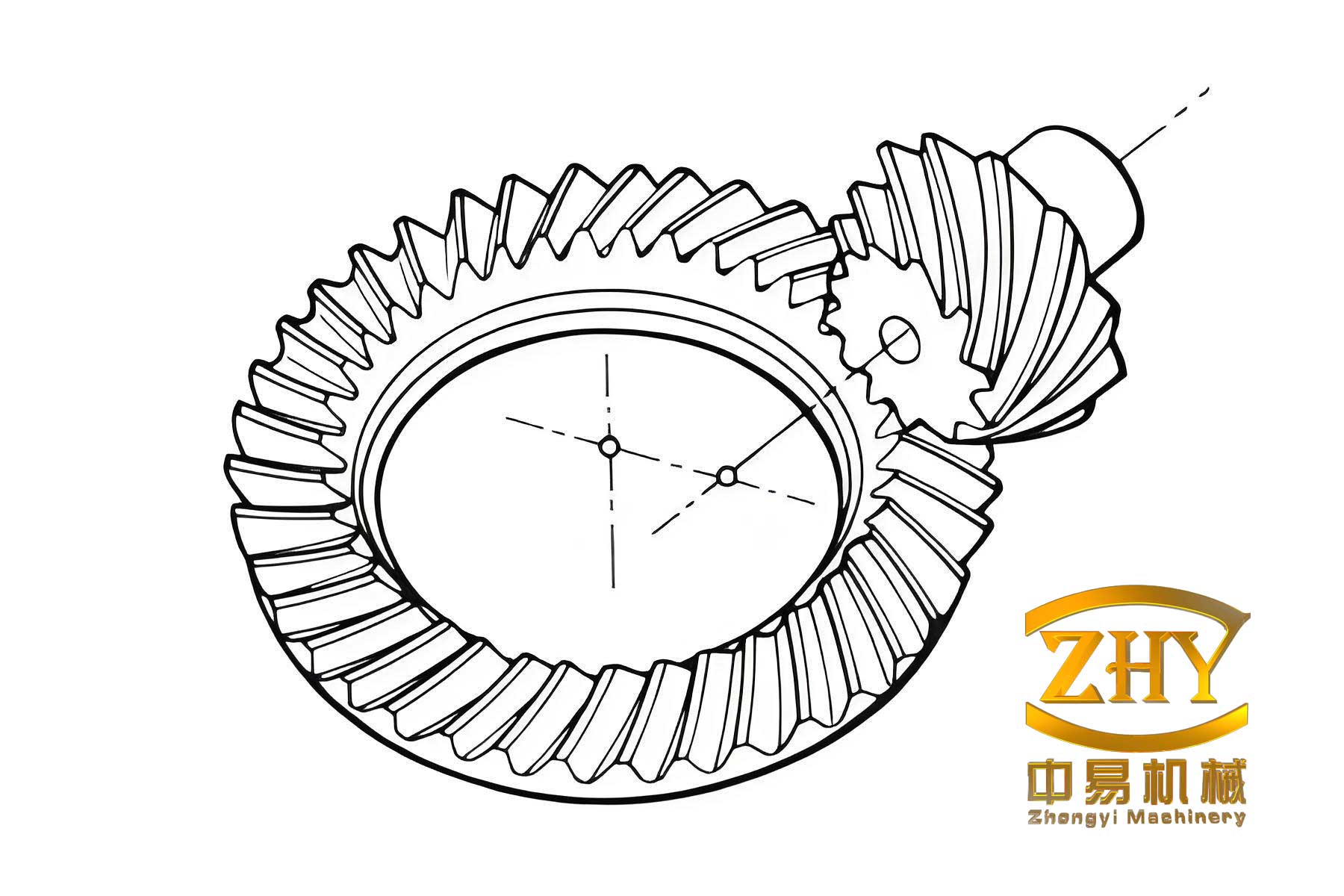
In my extensive experience working with automotive drivetrains, I have consistently recognized the superior performance of hypoid gears in rear axle differentials. These gears, characterized by their offset axes, offer significant advantages such as smoother transmission, reduced noise levels, uniform tooth surface wear, ease of grinding after heat treatment, and flexibility in vehicle layout due to axis offset. The application of hypoid gears is widespread in the central main reducers of automobile drive axles. However, designing these gears necessitates precise geometric parameter calculations to define their shape and dimensions. Traditionally, this involved manual computation using complex formulas, which was not only time-consuming but also prone to errors. To address these challenges, I embarked on developing a computer-aided design (CAD) program specifically for hypoid gears, aimed at providing a reliable and efficient pathway for designing the driving and driven gears in drive axle main reducers.
The geometric design of hypoid gears involves a multitude of parameters and interdependencies. Manual calculations typically rely on standardized tables, such as the “Universal Calculation Table for Circular Arc Hypoid Gears,” which contains numerous formulas. For instance, over forty distinct formulas might be required to fully define a gear pair. This process is cumbersome and susceptible to mistakes, especially when iterative adjustments are needed. My solution was to leverage computational power to automate these calculations. By developing a program on a personal computer, I could streamline the design process, ensuring accuracy and speed. This article details my methodology, focusing on formula simplification, program structure, and practical implementation, all from a first-person perspective as the developer and user of this CAD system.
The core of designing hypoid gears lies in determining geometric parameters like pitch angles, spiral angles, curvature radii, and cone distances. These parameters are derived from basic inputs such as tooth numbers, module, axis offset, and selected design factors. A critical aspect is the management of the taper coefficient and the curvature radius of the gear pitch cone. The taper coefficient directly influences the calculated curvature radius, which must closely match the standard cutter radius (nominal radius of the cutting tool). If the deviation exceeds allowable limits, the taper coefficient must be revised, and the curvature radius recalculated iteratively. This iterative refinement is essential for ensuring the correctness and functionality of the hypoid gear pair. My CAD program automates this iteration, eliminating manual guesswork.
To build the program, I first simplified the extensive calculation tables. The original set of formulas was condensed into a more manageable set, focusing on essential relationships. The simplification process, while omitted here for brevity, centered on the taper coefficient ($K$) and the pitch cone curvature radius ($R_c$). The key condition is that the computed $R_c$ must approximate the standard cutter radius ($R_0$) within a specified tolerance, typically not exceeding $\pm 1\%$. The governing equations for these parameters are foundational in hypoid gear geometry. For example, the curvature radius for the pinion (small gear) can be expressed as:
$$ R_c = \frac{d_{m1}}{2 \sin \gamma_1} + E $$
where $d_{m1}$ is the mean pitch diameter of the pinion, $\gamma_1$ is the pinion pitch angle, and $E$ is the axis offset. The taper coefficient $K$ relates to the gear tooth geometry and affects $R_c$ through the gear ratio and spiral angles. The spiral angles ($\beta_1$ for pinion, $\beta_2$ for gear) are crucial for defining the tooth orientation and are initially estimated. The design process for hypoid gears involves solving these interconnected parameters systematically.
My CAD program is structured into modular components to handle this systematic calculation. The program flow, as illustrated in the conceptual framework, begins with data input, proceeds through core computation modules with iterative loops for parameter adjustment, and concludes with output generation. Below is a summary of the primary modules and their functions:
| Module Name | Function Description | Key Parameters Involved |
|---|---|---|
| Data Input Module | Accepts basic and selected gear parameters from the user. | Tooth numbers ($z_1$, $z_2$), module ($m$), offset ($E$), gear ratio ($i$), face width ($b$), nominal cutter radius ($R_0$), preliminary pinion spiral angle ($\beta_1$), gear addendum coefficient ($h_{a2}^*$), gear working depth coefficient ($h_{w2}^*$), sum of pressure angles ($\Sigma\alpha$). |
| Calculation Module 1 | Computes initial geometric dimensions, starting with pinion mean pitch diameter. | Pinion mean pitch diameter $d_{m1} = m \cdot z_1 / \cos \beta_1$ (approximate), followed by preliminary pitch angles and spiral angles. |
| Iteration Loop Module | Adjusts taper coefficient $K$ iteratively to match computed curvature radius $R_c$ to $R_0$. | Taper coefficient $K$, computed $R_c$, tolerance check. Sub-modules increment or decrement $K$ based on deviation. |
| Calculation Module 2 | Finalizes all geometric parameters once $K$ is optimized. | Final pitch angles ($\gamma_1$, $\gamma_2$), spiral angles ($\beta_1$, $\beta_2$), face cone angles, root cone angles, cone distances, and axial positions. |
| Output Module | Generates and displays or prints all calculated parameters in tabular form. | Complete set of geometric data for both pinion and gear, ready for drafting. |
The iteration loop is the heart of the program. It ensures that the hypoid gears are designed within manufacturing constraints. The logic can be summarized as: while $|R_c – R_0| > \text{tolerance}$, if $R_c < R_0$, increase $K$; if $R_c > R_0$, decrease $K$. This loop continues until convergence. The mathematical representation of $R_c$ in terms of $K$ is derived from gear geometry principles. For circular arc teeth, a common relation is:
$$ R_c = R_0 \cdot \frac{\sin \beta_2}{\sin \beta_1} \cdot f(K, i, E) $$
where $f(K, i, E)$ is a function incorporating the taper coefficient, gear ratio, and offset. The exact formula varies based on the gear design system, but the iterative approach remains universal. This automation significantly reduces design time for hypoid gears.
To demonstrate the program’s efficacy, I will walk through a simulated design instance. Consider a single-reduction drive axle intended for a nominal axle load. The basic parameters for the hypoid gear pair are selected as follows:
| Parameter | Symbol | Value |
|---|---|---|
| Pinion tooth number | $z_1$ | 7 |
| Gear tooth number | $z_2$ | 41 |
| Axis offset | $E$ | 40 mm |
| Module | $m$ | 6.5 mm |
| Shaft angle | $\Sigma$ | 90° |
Additionally, the following design parameters are chosen based on experience and gear requirements:
| Parameter | Symbol | Value |
|---|---|---|
| Gear face width | $b$ | 60 mm |
| Gear ratio | $i = z_2/z_1$ | 5.857 |
| Preliminary pinion spiral angle | $\beta_1$ | 50° |
| Nominal cutter radius | $R_0$ | 152.4 mm |
| Gear addendum coefficient | $h_{a2}^*$ | 0.15 |
| Gear working depth coefficient | $h_{w2}^*$ | 1.70 |
| Sum of pressure angles | $\Sigma\alpha$ | 40° (e.g., 20°/20°) |
With these inputs, the program executes. In Calculation Module 1, the pinion mean pitch diameter is computed. An initial estimate is $d_{m1} \approx m \cdot z_1 / \cos \beta_1 = 6.5 \times 7 / \cos 50° \approx 70.85 \text{ mm}$. The program then enters the iteration loop. Starting with an assumed taper coefficient $K = 0.3$, it calculates a curvature radius $R_c = 148.2 \text{ mm}$. Since $R_c < R_0$ (152.4 mm), the taper coefficient is increased. After several iterations, at $K = 0.32$, $R_c = 152.1 \text{ mm}$, which is within the acceptable tolerance of ±0.2 mm. This value is then used in Calculation Module 2 to determine all other geometric parameters.
The final results for the hypoid gear pair are extensive. Below are the computed parameters for the pinion (active gear) and the gear (driven gear), as output by the program. These tables encapsulate the critical dimensions needed for manufacturing drawings.
| Parameter | Symbol | Value | Unit |
|---|---|---|---|
| Pinion pitch angle | $\gamma_1$ | 15.25° | deg |
| Pinion spiral angle | $\beta_1$ | 50.75° | deg |
| Pinion face angle | $\alpha_{f1}$ | 17.50° | deg |
| Pinion root angle | $\alpha_{r1}$ | 13.00° | deg |
| Distance from pinion face cone apex to gear axis | $A_{fp}$ | 245.3 | mm |
| Distance from pinion crown to gear axis | $C_p$ | 120.8 | mm |
| Distance from pinion root cone apex to gear axis | $A_{rp}$ | 260.1 | mm |
| Distance from pinion front crown to gear axis | $F_{cp}$ | 115.2 | mm |
| Parameter | Symbol | Value | Unit |
|---|---|---|---|
| Gear spiral angle | $\beta_2$ | 30.25° | deg |
| Distance from gear pitch cone apex to pinion axis | $\Delta$ | 85.6 | mm |
| Outer cone distance on gear pitch cone | $R_{e2}$ | 180.5 | mm |
| Gear face angle | $\alpha_{f2}$ | 72.50° | deg |
| Gear pitch angle | $\gamma_2$ | 74.75° | deg |
| Gear root angle | $\alpha_{r2}$ | 70.00° | deg |
| Theoretical gear outer diameter | $d_{a2}$ | 432.8 | mm |
| Distance from gear crown to pinion axis | $C_g$ | 95.4 | mm |
| Distance from gear face cone apex to pinion axis | $A_{fg}$ | 110.2 | mm |
| Distance from gear root cone apex to pinion axis | $A_{rg}$ | 125.7 | mm |
These parameters fully define the hypoid gear set for production. The program also calculates derived dimensions such as tooth thicknesses, addendum, dedendum, and clearance, but they are omitted here for brevity. The accuracy of these results hinges on the precise iteration of the taper coefficient and the underlying geometric models. The use of computer-aided design for hypoid gears ensures that all interdependent parameters are consistent and optimized.
Beyond basic geometry, the design of hypoid gears involves considerations for tooth contact analysis (TCA), stress calculations, and manufacturing setup. While my current program focuses on geometric parameter determination, it serves as a foundational step. For complete gear production, additional computations like cutting machine settings (e.g., for Gleason or Klingelnberg machines) are required. These are often handled by specialized software used by gear manufacturers. However, my CAD program provides the essential geometric data that can be exported to such systems or used directly for drafting.
The mathematical foundation for hypoid gear geometry is rich with formulas. To further illustrate, let’s delve into some key equations used in the program. The pitch angles are related by the shaft angle and gear ratio:
$$ \tan \gamma_1 = \frac{\sin \Sigma}{i + \cos \Sigma} \quad \text{for} \quad \Sigma = 90°, \quad \tan \gamma_1 = \frac{1}{i} $$
$$ \gamma_2 = \Sigma – \gamma_1 $$
The spiral angles satisfy the relation due to offset:
$$ \sin \beta_2 = \sin \beta_1 \cdot \frac{R_0}{R_c} \cdot g(K, E) $$
where $g$ is another function of taper and offset. The mean cone distance for the gear is:
$$ R_{m2} = \frac{d_{m2}}{2 \sin \gamma_2} $$
with $d_{m2} = m \cdot z_2 / \cos \beta_2$. The axis offset $E$ introduces complexity, linking the two gears’ geometries. The condition for correct meshing involves the equality of normal base pitches, which translates into constraints on the curvature radii and spiral angles. These relationships are embedded in the program’s algorithms.
Developing this CAD program required careful attention to numerical stability and user interface. I implemented it using a high-level programming language, ensuring modularity for future enhancements. The program prompts the user for input parameters, validates them, and then executes the calculations sequentially. The iterative loop uses a bisection method or incremental steps to adjust $K$, ensuring convergence within a few cycles. The output is formatted into clear tables, as shown above, and can be saved to files for documentation.
In practice, designing hypoid gears for different applications—such as heavy trucks, buses, or passenger cars—requires adjusting parameters like offset, module, and tooth numbers. My program is flexible enough to handle a wide range of inputs. For instance, increasing the offset $E$ generally allows for higher gear ratios and stronger pinions, but it also affects the spiral angles and curvature. The program automatically recalculates all dependent variables, providing designers with quick feedback on how changes impact the geometry.
The advantages of using computer-aided design for hypoid gears are manifold. First, it drastically reduces design time from days to minutes. Second, it minimizes human error, ensuring that gears are designed correctly the first time. Third, it facilitates optimization; by varying input parameters, designers can explore multiple configurations to achieve desired performance characteristics like strength, noise, and efficiency. Fourth, it standardizes the design process, making it easier to train new engineers and maintain consistency across projects. Finally, the digital output integrates seamlessly with modern CAD/CAM systems, enabling direct generation of toolpaths for manufacturing.
Looking ahead, there is potential to expand this program into a comprehensive hypoid gear design suite. Features like graphical visualization of gear teeth, integration with finite element analysis for stress evaluation, and automated generation of cutting machine settings would be valuable additions. Moreover, incorporating artificial intelligence for initial parameter selection could further streamline the process. The goal is to make hypoid gear design as efficient and accessible as possible, leveraging computational tools to push the boundaries of automotive drivetrain technology.
In conclusion, the computer-aided design of geometric parameters for hypoid gears represents a significant advancement over manual methods. My experience developing and using this program has demonstrated its reliability and efficiency. By automating complex calculations and iterative adjustments, it provides a robust foundation for designing high-performance hypoid gears for drive axles. As automotive industry demands evolve towards higher efficiency and lower noise, such CAD tools will become increasingly indispensable. The continued refinement of these programs will ensure that hypoid gears remain a cornerstone of modern vehicle drivetrains, meeting the challenges of future mobility.