
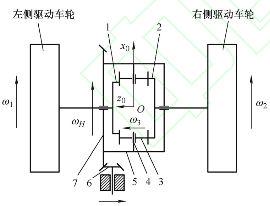
The basic configuration of a non circular gear differential is shown in the figure, which consists of non circular gears 1 and 2, small cylindrical spur gears (planetary gears) 3, planetary gear shaft 4, and planetary carrier (differential housing) 5. Among them, non circular gears 1 and 2 are sun gears, which are respectively connected to the left and right wheels. The engine power is transmitted to the two driving wheels through gears 6, gear 7, planetary carrier 5, planetary gear 3, and sun gears 1 and 2. From the perspective of mechanism composition and power transmission method, the non circular gear differential is completely the same as the ordinary bevel gear differential, without adding any additional mechanism.
The pitch curves of non circular gears 1 and 2 are the same and are constructed using equation (1). At the initial position, the phase angles of the two non circular gears differ by π/n. To ensure that there is no motion interference when the two sun gears rotate relative to each other in the differential, it is required that each planetary gear transmits the same motion. Therefore, the number of planetary gears must be the same as the order of the non circular gear, and the planetary gears must be uniformly distributed in the circumferential direction of the non circular gear.
In the figure, the basic parameters of each component are: the input speed of planetary carrier 5 is ω H. The rotational speeds of sun wheels 1 and 2 are respectively ω 1 and ω 2. The angular velocity of each planetary gear is the same, represented by planetary gear 3, and its rotational speed is ω 3。 The moment of inertia and radius of wheels are Ia and R respectively, the moment of inertia of non-circular gears 1 and 2 are I1 and I2, the moment of inertia of planetary carrier is IH, and the moment of inertia of planetary gear 3 for axis of rotation is Ix3.