
Because the tooth surface of spiral bevel gear is relatively complex, in order to ensure that the follow-up visual image tracking can accurately and efficiently capture the trace change, it is necessary to establish a mathematical three-dimensional model to preliminarily analyze and judge the contact tooth surface relationship.
The mathematical model is established by the derivation theory method, and the RC coordinate equation of the tooth surface of the spiral bevel gear SC is obtained according to the derivation theory method, as shown in formula (1):
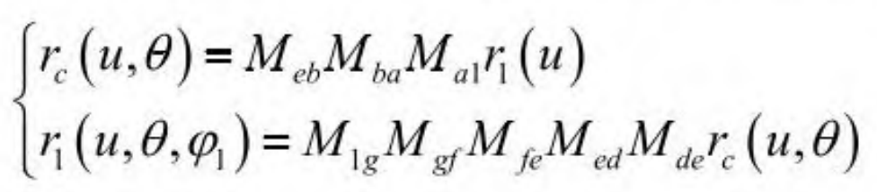
In formula (1), RC (U, θ) Represents the motion equation of spiral bevel gear, where u represents speed, θ Indicates the operating angle; r1(u, θ,φ 1) A vector equation representing the contact tooth surface; MEB, MBA, MA1, m1g, MGF, MFE, Med and MDE respectively represent the directional distance calculation values of spiral bevel gears in the derivation theory method; EB, Ba, A1, 1g, GF, Fe, EB and de respectively represent the tangent, sine, cosine, positive side, tangential side, height and center point of the gear.
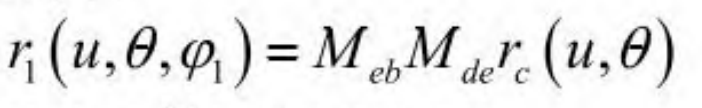
The vector equation R1 (U, θ,φ 1) As shown in formula (2):
The unit normal vector formed is shown in formula (3):
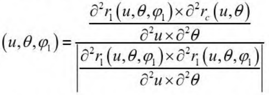
In formula (3), 2 ∂ represents the engagement parameter. According to the infinite meshing principle between spiral bevel gears, the tooth surface meshing equation of spiral bevel gears in the movement process is shown in formula (4):
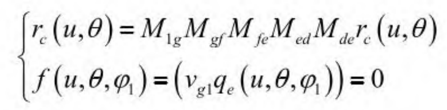
In formula (4), f represents the vector equation of the non-contact tooth surface; Vg1 represents relative acceleration. When there is a positive correlation between the speed of the spiral bevel gear and the speed of the tooth surface, θ,φ 1) It is 0, indicating that the speed of the two is the same, there is no reverse friction, and the contact surface has the maximum fit; Whereas f (U, θ,φ 1) If it is not 0, it indicates that the speeds of the two are inconsistent, the fitting degree of the contact surface does not reach the maximum value, and there is also non-contact. It can be determined that f (U, θ,φ 1) If it is 0, there are traces in the contact area, which can greatly reduce the probability of false judgment and improve the efficiency of algorithm implementation in visual tracking.