
Hypoid bevel gears are extensively employed in the main reducers of automotive drive axles because of their large transmission ratio, smooth operation, and high load-carrying capacity. As a critical component in vehicle power transmission, the hypoid bevel gear directly influences the reliability, safety, and comfort of the entire drivetrain. With the continuous development of the automotive industry, the requirements for the meshing performance of hypoid bevel gears have become increasingly stringent. Poor meshing performance not only increases vibration and noise but also accelerates wear and reduces service life. Therefore, analyzing the contact characteristics and optimizing the meshing performance of hypoid bevel gears is of substantial practical significance.
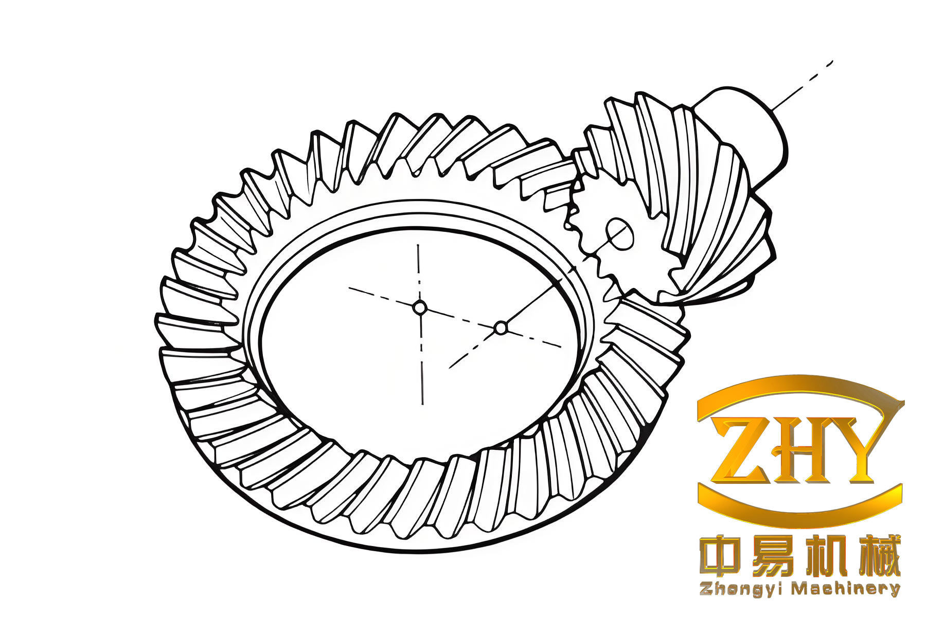
In this research, I establish a mathematical model for the hypoid bevel gear tooth surface based on the cutting principle, perform tooth contact analysis to obtain the contact pattern and transmission error, and propose a meshing performance optimization method that comprehensively considers both the contact pattern and transmission error. Furthermore, I introduce installation errors into the meshing model, study the sensitivity of meshing performance to different types of installation errors, and optimize the machine tool settings to reduce this sensitivity. Finally, I verify the proposed methods through cutting experiments, tooth surface error measurements, and rolling tests. The entire investigation is conducted from a first-person perspective, and the main contributions are summarized through equations, tables, and experimental data.
The hypoid bevel gear is a special type of spiral bevel gear. Unlike ordinary spiral bevel gears, the pinion and gear axes of a hypoid bevel gear are offset, which allows the pinion to have a larger diameter and thus greater strength and rigidity. This offset also enables the hypoid bevel gear to transmit motion between intersecting axes with a large transmission ratio, making it ideal for automotive drive axles. The two most common manufacturing methods for hypoid bevel gears are the face-milling method with intermittent indexing and the face-hobbing method with continuous indexing. In this work, I adopt the face-milling method because it allows both cutting and grinding on the same machine and provides high accuracy.
To analyze the contact characteristics of a hypoid bevel gear, I first establish the tooth surface equations. The cutting process can be modeled by considering the relative motion between the cutter, the machine tool, and the workpiece. The cutter head rotates around its own axis, and the blade edges generate a conical surface. By transforming this conical surface into the workpiece coordinate system, I obtain the tooth surface equation. The mathematical derivation is presented in the following sections.
1. Tooth Surface Equation and Three-Dimensional Model
The hypoid bevel gear tooth surface is generated by a rotating cutter head. For the gear (the larger wheel), I use the forming method, while for the pinion (the smaller wheel), I use the tilting method. The cutter head coordinate system is established first. For the gear, the inner and outer blades generate the convex and concave surfaces, respectively. The radial vector and unit normal vector of a point on the cutter conical surface can be expressed as:
$$
\mathbf{r}_c = \begin{bmatrix}
(r_d – u_c \sin\alpha_c)\cos\theta_c \\
(r_d – u_c \sin\alpha_c)\sin\theta_c \\
-u_c \cos\alpha_c \\
1
\end{bmatrix}
$$
$$
\mathbf{n}_c = \frac{\frac{\partial \mathbf{r}_c}{\partial u_c} \times \frac{\partial \mathbf{r}_c}{\partial \theta_c}}{\left| \frac{\partial \mathbf{r}_c}{\partial u_c} \times \frac{\partial \mathbf{r}_c}{\partial \theta_c} \right|}
= \begin{bmatrix}
-\cos\alpha_c \cos\theta_c \\
-\cos\alpha_c \sin\theta_c \\
-\sin\alpha_c
\end{bmatrix}
$$
Here, \(r_d\) is the cutter tip radius, \(u_c\) is the blade edge parameter, \(\alpha_c\) is the blade profile angle, and \(\theta_c\) is the cutter rotation angle. For the gear, the machine tool coordinate system \(S_g\), the auxiliary coordinate system \(S_h\), and the gear blank coordinate system \(S_m\) are defined. The transformation from the cutter coordinate system \(S_c\) to the gear blank coordinate system \(S_m\) is given by:
$$
\mathbf{r}_m = \mathbf{M}_{mg} \mathbf{M}_{gc} \mathbf{r}_c
$$
$$
\mathbf{n}_m = \mathbf{L}_{mg} \mathbf{L}_{gc} \mathbf{n}_c
$$
where \(\mathbf{M}_{mg}\) and \(\mathbf{M}_{gc}\) are 4×4 transformation matrices, and \(\mathbf{L}_{mg}\) and \(\mathbf{L}_{gc}\) are their 3×3 rotational submatrices. The explicit forms are:
$$
\mathbf{M}_{mg} = \begin{bmatrix}
\cos\gamma_1 & 0 & \sin\gamma_1 & X_1 \\
0 & 1 & 0 & 0 \\
-\sin\gamma_1 & 0 & \cos\gamma_1 & 0 \\
0 & 0 & 0 & 1
\end{bmatrix}
$$
$$
\mathbf{M}_{gc} = \begin{bmatrix}
1 & 0 & 0 & H_1 \\
0 & 1 & 0 & V_1 \\
0 & 0 & 1 & 0 \\
0 & 0 & 0 & 1
\end{bmatrix}
$$
For the pinion, the cutting process involves a tilting mechanism and a cutter rotation mechanism. The pinion tooth surface is generated by the envelope of the cutter family. The meshing equation between the cutter and the pinion blank is:
$$
\mathbf{n}_q \cdot \mathbf{v}_q = 0
$$
where \(\mathbf{n}_q\) is the unit normal vector of the cutter surface in the machine coordinate system \(S_q\), and \(\mathbf{v}_q\) is the relative velocity between the cutter and the pinion blank. After solving this equation, the pinion tooth surface equation is obtained as:
$$
\mathbf{r}_w = \mathbf{M}_{wf} \mathbf{M}_{fu} \mathbf{M}_{uq} \mathbf{M}_{qr} \mathbf{M}_{rA} \mathbf{M}_{Ap} \mathbf{r}_p
$$
$$
\mathbf{n}_w = \mathbf{L}_{wf} \mathbf{L}_{fu} \mathbf{L}_{uq} \mathbf{L}_{qr} \mathbf{L}_{rA} \mathbf{L}_{Ap} \mathbf{n}_p
$$
To solve the tooth surface equations numerically, I discretize the tooth surface into a 5×9 grid. The projection of the tooth surface onto the axial section is used to determine the coordinates of 45 discrete points. For each point, I solve the nonlinear equations using the Newton-Raphson method. The initial guess is taken from the neighboring point, and the solution path is planned to ensure convergence. The discrete points are then imported into a CAD environment to construct the three-dimensional model of the hypoid bevel gear.
Table 1 lists the basic blank parameters of the hypoid bevel gear pair used in this study. Table 2 presents the machine tool settings for the gear and the pinion.
| Parameter | Pinion | Gear |
|---|---|---|
| Hand of spiral | Left | Right |
| Number of teeth | 9 | 39 |
| Face width (mm) | 59.25 | 54.00 |
| Spiral angle (°) | 48.36 | 36.54 |
| Offset (mm) | 35.00 | |
| Whole depth (mm) | 17.07 | 16.90 |
| Pitch cone angle (°) | 15.65 | 74.01 |
| Face cone angle (°) | 19.60 | 76.30 |
| Root cone angle (°) | 14.95 | 70.57 |
| Outer cone distance (mm) | 97.19 | 84.72 |
| Parameter | Gear | Pinion concave | Pinion convex |
|---|---|---|---|
| Cutter nominal diameter (mm) | 304.8 | 298.54 | 299.66 |
| Blade profile angle (°) | 22.30 | 14.00 | 35.00 |
| Cutter tip radius (mm) | 1.90 | 2.47 | 2.47 |
| Tilt angle (°) | — | 15.07 | 15.50 |
| Swivel angle (°) | — | 248.96 | 267.48 |
| Radial cutter position (mm) | — | 139.67 | 141.52 |
| Angular cutter position (°) | — | 55.64 | 47.11 |
| Machine root angle (°) | 70.32 | -2.00 | -3.59 |
| Horizontal wheel position (mm) | -1.05 | -4.34 | 5.94 |
| Vertical wheel position (mm) | 122.01 | 34.94 | 36.13 |
| Bed position (mm) | — | 34.79 | 50.96 |
| Roll ratio | — | 4.19 | 4.37 |
2. Tooth Contact Analysis of the Hypoid Bevel Gear
Tooth contact analysis (TCA) is a mathematical simulation of the meshing process of a hypoid bevel gear pair. It allows me to predict the contact pattern and transmission error without physically manufacturing the gears. The first step is to establish the meshing coordinate system. The gear and pinion are assembled according to their theoretical mounting positions. The initial contact point on the gear is selected at the center of the tooth surface. The corresponding point on the pinion is found by solving the meshing equations. The contact equations in the meshing coordinate system are:
$$
\mathbf{r}_m^{(T)} = \mathbf{r}_w^{(T)}
$$
$$
\mathbf{n}_m^{(T)} = \mathbf{n}_w^{(T)}
$$
These vector equations yield five independent scalar equations. The unknowns are the pinion surface parameters and the rotation angles of both gears. By incrementing the pinion rotation angle, I obtain a series of contact points that form the contact path. The contact ellipse at each point is determined by the induced normal curvature and geodesic torsion. The major and minor semi-axes of the contact ellipse are:
$$
l_{\max} = \sqrt{\frac{2\delta}{K_{\min}}}, \quad l_{\min} = \sqrt{\frac{2\delta}{K_{\max}}}
$$
where \(\delta\) is the amount of red lead powder thickness, typically 0.00635 mm, and \(K_{\min}\) and \(K_{\max}\) are the extremal induced normal curvatures. The orientation of the contact ellipse is determined by the direction of the minimum induced normal curvature. The contact pattern is then obtained by projecting all contact ellipses onto the tooth surface.
The transmission error is defined as the difference between the actual rotation angle of the gear and the theoretical rotation angle for a given pinion rotation. It is calculated as:
$$
\Delta \varepsilon = \phi_w – \frac{z_1}{z_2} \phi_m
$$
where \(\phi_w\) and \(\phi_m\) are the actual rotation angles of the gear and pinion, and \(z_1\) and \(z_2\) are their tooth numbers. The transmission error curve is plotted as a function of the pinion rotation angle. For a well-designed hypoid bevel gear pair, the transmission error curve should be concave downward and adjacent curves should intersect. The intersection point ensures smooth transition between consecutive tooth pairs.
Figure 1 shows the contact pattern and transmission error obtained from the initial machine tool settings. I observed several defects: edge contact occurs, the inclination angle of the contact path is too large, and the transmission error curves do not intersect. These defects lead to unstable transmission, increased vibration, and higher noise. Therefore, an optimization method is required to improve the meshing performance of the hypoid bevel gear.
3. Meshing Performance Optimization
To optimize the meshing performance of the hypoid bevel gear, I select three objectives: the contact area \(S\), the inclination angle of the contact path \(\gamma\), and the ordinate of the transmission error intersection point \(\delta\). The objective function is formulated as:
$$
f(S,\gamma,\delta) = \frac{|S – S_1|}{\varepsilon_1} + \frac{|\gamma – \gamma_1|}{\varepsilon_2} + \frac{|\delta – \delta_1|}{\varepsilon_3}
$$
where \(S_1\), \(\gamma_1\), and \(\delta_1\) are the target values, and \(\varepsilon_1\), \(\varepsilon_2\), and \(\varepsilon_3\) are the optimization tolerances. The control parameters are the normal curvatures \(k_1\), \(k_2\) and the geodesic torsion \(k_3\) of the pinion cutting pitch cone. The search space is defined by scaling factors \(a_0\), \(b_0\), and \(c_0\):
$$
k_1^T = [(1-a_0)k_1^0, (1+a_0)k_1^0]
$$
$$
k_2^T = [(1-b_0)k_2^0, (1+b_0)k_2^0]
$$
$$
k_3^T = [(1-c_0)k_3^0, (1+c_0)k_3^0]
$$
The constraints are defined by the feasible region of the contact pattern. The shrinkage rates \(H_1\) and \(H_2\) are set to 0.85–0.95, meaning that the contact pattern must remain within a reduced tooth surface boundary to avoid edge contact under load. I use an improved particle swarm optimization (PSO) algorithm to solve this optimization problem. The conventional PSO update equations are:
$$
V_i^{t+1} = \omega V_i^t + c_1 r_1 (P_{ibest}^t – X_i^t) + c_2 r_2 (G_{best}^t – X_i^t)
$$
$$
X_i^{t+1} = X_i^t + V_i^{t+1}
$$
To overcome the shortcomings of fixed inertia weight and premature convergence, I introduce an adaptive inertia weight and the Metropolis criterion from simulated annealing. The adaptive inertia weight is:
$$
\omega(t) = (\omega_{start} – \omega_{end}) \tan(0.785(1 – (t/t_{\max})^k)) + \omega_{end}
$$
where \(\omega_{start} = 0.9\), \(\omega_{end} = 0.4\), \(t_{\max} = 100\), and \(k = 0.6\). The Metropolis criterion allows the algorithm to accept worse solutions with a probability \(P = \exp(\Delta f / T)\), where \(\Delta f = f(pbest) – f(x_i)\) and \(T\) is the annealing temperature. This helps the algorithm escape local optima.
After 36 iterations, the objective function converges to 0.016703. The optimized contact area is 179.631 mm², the inclination angle is 25.221°, and the transmission error intersection ordinate is \(-5.029 \times 10^{-5}\) rad. The errors relative to the target values are 0.205%, 0.8853%, and 0.58%, respectively, all within the specified tolerances. Table 3 lists the optimized pinion machine tool settings.
| Parameter | Optimized value |
|---|---|
| Blade profile angle (°) | 14.00 |
| Cutter tip diameter (mm) | 301.61 |
| Cutter tip radius (mm) | 2.47 |
| Tilt angle (°) | 15.42 |
| Swivel angle (°) | 249.72 |
| Radial cutter position (mm) | 137.21 |
| Angular cutter position (°) | 56.82 |
| Machine root angle (°) | -1.85 |
| Horizontal wheel position (mm) | -5.12 |
| Bed position (mm) | 34.18 |
| Vertical wheel position (mm) | 33.86 |
| Roll ratio | 4.09 |
To validate the optimization, I perform finite element contact analysis using ANSYS Workbench. The gear and pinion are modeled with 20CrMnTi material properties: elastic modulus 207 GPa, Poisson’s ratio 0.25, and density 7800 kg/m³. Frictional contact with a coefficient of 0.06 is used. The contact surfaces are refined to a mesh size of 0.25 mm. A torque of 100 N·m is applied to the pinion. The simulation results show that the optimized hypoid bevel gear pair has no edge contact, and the contact pattern is well distributed along the tooth length. The simulation results agree well with the theoretical predictions.
4. Influence of Installation Errors and Sensitivity Optimization
Installation errors inevitably occur during the assembly of a hypoid bevel gear pair. The main types are the gear axial error \(\Delta J\), the pinion axial error \(\Delta H\), the offset error \(\Delta V\), and the shaft angle error \(\Delta \psi\). These errors shift the contact pattern and change the transmission error, thereby degrading the meshing performance. I incorporate these errors into the meshing coordinate system and derive the modified meshing equations. The gear tooth surface vector and normal vector in the meshing coordinate system become:
$$
\mathbf{r}_m^{(T)} = \mathbf{M}_{mT} \mathbf{M}_{m} \mathbf{r}_m
$$
$$
\mathbf{n}_m^{(T)} = \mathbf{L}_{mT} \mathbf{L}_{m} \mathbf{n}_m
$$
where the transformation matrices include the installation error terms. The pinion side is treated similarly. By solving the new meshing equations, I obtain the contact pattern and transmission error under various installation errors. To quantify the influence, I define the sensitivity coefficient of a contact pattern parameter \(f_i\) with respect to an installation error \(\Delta e\) as:
$$
F_i = \frac{\Delta f_i}{\Delta e}
$$
where \(f_i\) can be the contact area \(S\), the centroid coordinates \(X\) and \(Y\), or the inclination angle \(\gamma\). Table 4 summarizes the sensitivity coefficients for the initial design. The offset error \(\Delta V\) has the largest influence on all parameters, while the gear axial error \(\Delta J\) has the smallest influence.
| Parameter | \(F_S\) | \(F_X\) | \(F_Y\) | \(F_\gamma\) |
|---|---|---|---|---|
| \(\Delta J\) | 22.568 | 4.168 | 0.612 | 4.956 |
| \(\Delta H\) | 8.619 | 5.795 | 2.543 | 6.521 |
| \(\Delta V\) | 10.076 | 12.863 | 3.258 | 13.258 |
| \(\Delta \psi\) | 13.352 | 8.085 | 2.671 | 4.938 |
Based on these sensitivity coefficients, I construct a weighted objective function to minimize the comprehensive sensitivity of the contact pattern to installation errors:
$$
\min f = a_1 S_s + a_2 S_x + a_3 S_y + a_4 S_\gamma
$$
$$
a_1 + a_2 + a_3 + a_4 = 1
$$
where \(S_s\), \(S_x\), \(S_y\), and \(S_\gamma\) are the comprehensive sensitivity coefficients of the contact area, centroid abscissa, centroid ordinate, and inclination angle, respectively. The weighting factors are chosen according to the relative magnitude of the sensitivities. I again use the improved PSO algorithm to optimize the pinion cutting pitch cone parameters. The optimized machine tool settings are listed in Table 5. After optimization, the sensitivity coefficients are generally reduced, as shown in Table 6. For example, the sensitivity to the offset error is reduced by up to 12.5%, and the sensitivity to the shaft angle error is reduced by up to 12.6%. Although a few coefficients increase slightly due to the coupling between parameters, the overall comprehensive sensitivity is significantly lowered.
| Parameter | Optimized value |
|---|---|
| Blade profile angle (°) | 14.00 |
| Cutter tip diameter (mm) | 301.18 |
| Cutter tip radius (mm) | 2.47 |
| Tilt angle (°) | 15.75 |
| Swivel angle (°) | 249.85 |
| Radial cutter position (mm) | 137.68 |
| Angular cutter position (°) | 55.97 |
| Machine root angle (°) | -1.92 |
| Horizontal wheel position (mm) | -4.96 |
| Bed position (mm) | 34.63 |
| Vertical wheel position (mm) | 33.93 |
| Roll ratio | 4.16 |
| Parameter | \(F_S\) | \(F_X\) | \(F_Y\) | \(F_\gamma\) |
|---|---|---|---|---|
| \(\Delta J\) | 20.463 | 4.301 | 0.591 | 4.566 |
| \(\Delta H\) | 8.809 | 5.186 | 2.401 | 5.896 |
| \(\Delta V\) | 10.268 | 11.725 | 3.296 | 11.607 |
| \(\Delta \psi\) | 11.670 | 7.558 | 2.622 | 5.033 |
The optimization results indicate that the hypoid bevel gear pair becomes more tolerant to installation errors. Under the same installation error, the contact pattern shift is smaller than that of the initial design, and the transmission error curves still intersect, ensuring smooth transmission.
5. Experimental Verification
To verify the proposed methods, I conduct cutting experiments, tooth surface error measurements, and rolling tests on both the initial and optimized hypoid bevel gear pairs. The gear is manufactured by the forming method, and the pinion by the tilting method. The cutting processes are performed on CNC spiral bevel gear milling machines. The tooth surface errors are measured using a gear measuring instrument with a 5×9 grid. The maximum deviations for the pinion convex and concave surfaces are 0.0092 mm and 0.0088 mm, respectively, both within the allowable tolerance of 0.01 mm.
The rolling tests are carried out on a semi-automatic bevel gear rolling tester. Red lead powder with a thickness of 0.00635 mm is applied to the tooth surfaces. After 30 seconds of rolling, the contact patterns are observed. The optimized hypoid bevel gear pair exhibits a larger contact area, a smaller inclination angle, and no edge contact. The contact patterns obtained from the rolling tests are consistent with the theoretical predictions.
The transmission noise is also measured during the rolling tests. For each gear pair, I record 10 noise values at different times and take the average. The results are presented in Table 7. The average noise of the initial design is 69.3 dB, while that of the optimized design is 59.9 dB, representing a reduction of 13.6%. This significant reduction confirms that the optimization method effectively improves the meshing performance of the hypoid bevel gear.
| Measurement | Initial design (dB) | Optimized design (dB) |
|---|---|---|
| 1 | 69.1 | 59.7 |
| 2 | 69.5 | 60.2 |
| 3 | 69.0 | 59.8 |
| 4 | 69.4 | 59.6 |
| 5 | 69.2 | 60.0 |
| 6 | 69.6 | 59.9 |
| 7 | 69.3 | 59.5 |
| 8 | 69.1 | 60.1 |
| 9 | 69.5 | 59.8 |
| 10 | 69.3 | 60.3 |
| Average | 69.3 | 59.9 |
For the installation error tests, I adjust the offset error to +0.5 mm and -0.5 mm and observe the contact pattern. When the offset error is negative, the contact pattern shifts toward the heel of the gear, and the inclination angle increases. When the offset error is positive, the contact pattern shifts toward the toe, and the inclination angle decreases. These trends agree with the theoretical analysis, further validating the installation error model.
6. Conclusion
In this work, I have conducted a comprehensive study on the contact characteristics and meshing performance optimization of hypoid bevel gears. The main conclusions are as follows:
1. I established the tooth surface equations for both the gear and pinion based on the cutting principle. By discretizing the tooth surface and solving the nonlinear equations, I obtained the three-dimensional model of the hypoid bevel gear.
2. I performed tooth contact analysis to obtain the contact pattern and transmission error. The initial design exhibited edge contact, a large inclination angle, and discontinuous transmission error curves. I proposed a meshing performance optimization method that considers both the contact pattern and transmission error. Using an improved PSO algorithm with adaptive inertia weight and the Metropolis criterion, I optimized the pinion machine tool settings. The optimized design eliminated edge contact and achieved the desired contact pattern and transmission error.
3. I introduced installation errors into the meshing model and analyzed the sensitivity of the contact pattern parameters to different error types. The offset error had the largest influence. I constructed a weighted sensitivity objective function and optimized the pinion cutting parameters to reduce the comprehensive sensitivity. The optimized hypoid bevel gear pair showed improved tolerance to installation errors.
4. I conducted cutting experiments, tooth surface error measurements, and rolling tests. The optimized hypoid bevel gear pair had a more favorable contact pattern, no edge contact, and a 13.6% reduction in transmission noise. The experimental results validated the proposed optimization methods.
Overall, the research presented in this article provides a systematic approach for the contact analysis and meshing performance optimization of hypoid bevel gears. The proposed methods can be applied to improve the design and manufacturing of hypoid bevel gears in automotive drive axles and other industrial applications.