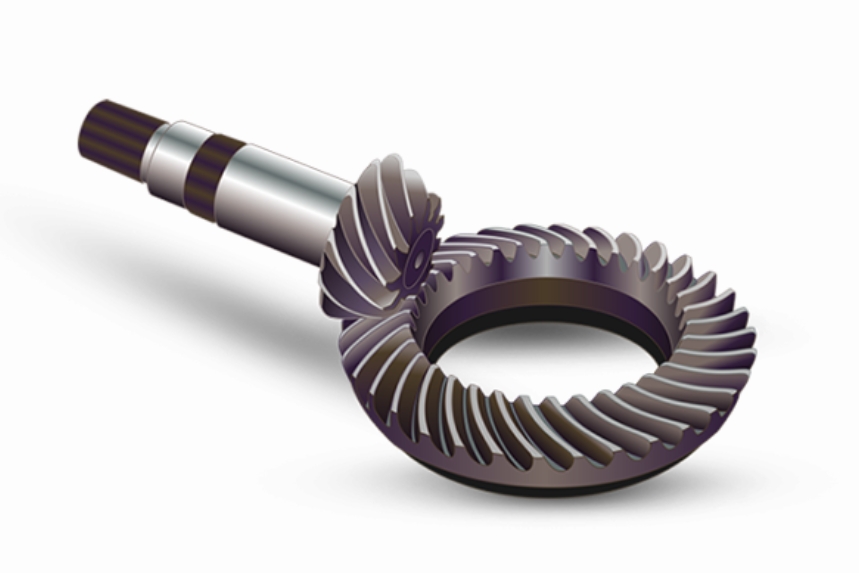
The contact characteristics of spiral bevel gears critically influence their transmission efficiency, load capacity, and operational stability. This study investigates the meshing behavior of double circular-arc spiral bevel gears under nutation drive conditions through finite element analysis (FEA). Key parameters such as contact stress distribution, load-sharing ratio, and meshing patterns under varying loads and installation errors are systematically analyzed.

Mathematical Modeling of Double Circular-Arc Spiral Bevel Gears
The tooth profile of the double circular-arc spiral bevel gear is defined by two conjugate circular arcs in the normal section. The parametric equations for the concave and convex arcs in the local coordinate system \( S_n(x_n, y_n, z_n) \) are expressed as:
$$
\mathbf{r}_{ni} = \begin{pmatrix}
r_i \sin\alpha_i + E_i \\
r_i \cos\alpha_i + F_i \\
0
\end{pmatrix} \quad (i = 1, 2, \ldots, 8)
$$
where \( r_i \), \( \alpha_i \), and \( (E_i, F_i) \) represent the radius, pressure angle, and center coordinates of each arc segment, respectively. The tooth surface is generated by sweeping the profile along a logarithmic spiral with helix angle \( \beta \):
$$
\begin{cases}
x’_p = x_p + [\pm (\rho_j – l_j)] \sin(\theta – \Delta\theta_j + \beta) \\
y’_p = y_p – [\pm (\rho_j – l_j)] \cos(\theta – \Delta\theta_j + \beta)
\end{cases}
$$
where \( \rho_j \) and \( l_j \) denote the radius and offset of the spiral curve. Coordinate transformations between the crown gear and nutating components yield the final tooth surfaces of the external and internal spiral bevel gears.
| Parameter | External Gear | Internal Gear |
|---|---|---|
| Number of Teeth | 26 | 28 |
| Module at Toe (mm) | 2 | 2 |
| Nutation Angle (°) | 5 | 5 |
| Spiral Angle (°) | 25 | 25 |
| Cone Distance (mm) | 60 | 60 |
Finite Element Modeling and Contact Analysis
A seven-tooth sector model was developed in ANSYS Workbench to balance computational efficiency and accuracy. Key modeling considerations include:
- Material properties: Elastic modulus = 210 GPa, Poisson’s ratio = 0.3
- Contact definition: Frictional coefficient = 0.1
- Boundary conditions: Fixed external gear, torque-loaded internal gear
- Mesh configuration: 187,370 tetrahedral elements
The transient contact analysis reveals three distinct meshing phases:
- Single-point contact at convex tooth surface (toe region)
- Double-point contact with simultaneous convex/concave engagement
- Single-point contact at concave tooth surface (heel region)
The maximum contact stress occurs near the toe during final disengagement due to reduced contact area:
$$
\sigma_{\text{max}} = \sqrt{\frac{F}{\pi} \left( \frac{1-\nu_1^2}{E_1} + \frac{1-\nu_2^2}{E_2} \right)^{-1} \left( \frac{1}{R_1} + \frac{1}{R_2} \right)}
$$
Load-Dependent Transmission Performance
Transmission characteristics show significant load dependence:
| Torque (Nm) | Contact Ratio | Peak Load Share |
|---|---|---|
| 50 | 1.92 | 100% |
| 120 | 2.31 | 85.9% |
| 150 | 2.54 | 78.8% |
Higher loads increase contact ratio (\( \varepsilon \)) while reducing load concentration:
$$
\varepsilon = \frac{\Delta\phi}{\Delta\lambda} \propto \ln(T^{0.7})
$$
Installation Error Sensitivity
Two critical error types were analyzed:
| Error Type | Direction | Δσmax |
|---|---|---|
| Offset (ΔC) | +0.05 mm | -12% |
| -0.05 mm | +18% | |
| Nutation Angle (Δα) | +0.05° | +22% |
| -0.05° | -9% |
Negative offset and positive nutation angle errors exacerbate edge loading, increasing stress by 18–22%. The load-sharing coefficient \( C \) varies nonlinearly with errors:
$$
C = \frac{F_j}{\sum F_j} \approx 1.2e^{3.5|\Delta|} \quad (\Delta: \text{Normalized error})
$$
Conclusions
1. Double circular-arc spiral bevel gears exhibit adaptive load distribution through phased single/double contact transitions, with maximum stress at the toe region (1.15×heel stress).
2. Increasing torque from 50 Nm to 150 Nm enhances contact ratio by 32% while reducing peak load concentration by 21%, promoting stable power transmission.
3. Installation errors ≤0.05 mm/° cause ≤22% stress variation. Negative offset and positive nutation errors require strict control (<0.03 mm/° for precision applications).
4. The hybrid analytical-FEA methodology enables accurate prediction of spiral bevel gear performance under complex nutation kinematics, supporting optimal design of compact high-ratio reducers.
