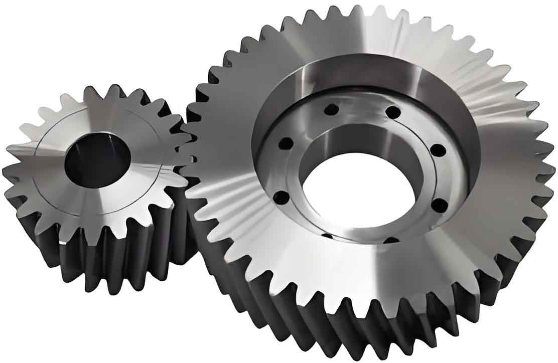
This study investigates the contact fatigue crack propagation mechanism in cylindrical gears with variable hyperbolic circular-arc-tooth-trace (VH-CATT). A numerical model for analyzing contact ellipses is established based on curvature characteristics, enabling precise identification of crack-prone zones through finite element simulations. The extended finite element method (XFEM) is employed to simulate fatigue crack growth, while stress intensity factors (SIFs) are analyzed to evaluate the effects of modulus, tooth line radius, and crack preset angles.

1. Theoretical Analysis of VH-CATT Cylindrical Gear
1.1 Tooth Surface Formulation
The tooth surface equations for VH-CATT cylindrical gears are derived using coordinate transformations between cutting tools and workpiece systems. For concave and convex tooth surfaces:
$$r^{(c)}_i = \left[ u\sin\alpha \pm R_T, 0, u\cos\alpha \mp R_T \tan\left(\frac{\pi}{4}\right) \right]$$
1.2 Contact Ellipse Analysis
The comprehensive curvature radii in tooth line (Rₓ) and profile (Rᵧ) directions determine contact characteristics:
$$
R_x = \frac{R_p^x R_g^x}{R_p^x + R_g^x}, \quad R_y = \frac{R_p^y R_g^y}{R_g^y – R_p^y}
$$
Contact ellipse dimensions are calculated using Hertzian theory:
$$
a = \sqrt[3]{\frac{3\omega k_a}{2E(A+B)}}, \quad b = \sqrt[3]{\frac{3\omega k_b}{2E(A+B)}}
$$
| Gear Parameter | Driving Gear | Driven Gear |
|---|---|---|
| Number of Teeth | 29 | 21 |
| Module (mm) | 4 | 4 |
| Tooth Line Radius (mm) | 200 | 200 |
| Face Width (mm) | 40 | 40 |
2. Crack Propagation Modeling
2.1 XFEM Implementation
The displacement approximation function for crack modeling combines standard shape functions with enrichment terms:
$$
u^h(X) = \sum_{i=1}^N N_i(X)u_i + \sum_{j=1}^S N_j(X)H(X)a_j + \sum_{k=1}^T N_k(X)\left(\sum_{l=1}^4 \Phi_l^k(X)b_l^k\right)
$$
2.2 Critical Crack Parameters
| Crack Stage | Length (mm) | SIF Dominance |
|---|---|---|
| Initiation | <0.3 | Mixed-mode (KI, KII, KIII) |
| Short Crack | 0.3-1.0 | KI Dominance |
| Long Crack | >1.0 | Pure Mode I |
3. Stress Intensity Factor Analysis
The M-integral method calculates SIFs for three-dimensional cracks:
$$
M^{(1,2)} = \int_V \left[\sigma_{ij}^{(1)}\frac{\partial u_i^{(2)}}{\partial x_j} + \sigma_{ij}^{(2)}\frac{\partial u_i^{(1)}}{\partial x_j} – W^{(1,2)}\delta_{1j}\right] \frac{\partial q}{\partial x_j} dV
$$
3.1 Modulus Effects
Larger modules increase SIFs during long crack propagation:
$$
K_I^{a=5\,\text{mm}} = 18.7\,\text{MPa}\sqrt{\text{m}} \quad (m=5\,\text{mm}) \quad \text{vs} \quad 15.2\,\text{MPa}\sqrt{\text{m}} \quad (m=3\,\text{mm})
$$
3.2 Tooth Line Radius Influence
| Radius (mm) | KI at a=5mm (MPa√m) |
|---|---|
| 100 | 20.1 |
| 200 | 18.7 |
| 300 | 16.3 |
3.3 Crack Preset Angle Impact
Angled cracks exhibit complex SIF evolution:
$$
\theta = 135^\circ \Rightarrow 22\%\ \text{higher } K_I \text{ than } 90^\circ \text{ at } a=3\,\text{mm}
$$
4. Crack Propagation Dynamics
The cylindrical gear demonstrates distinct propagation phases:
- Initiation Phase (0-300 cycles): Radial growth dominates (0.2-0.5 mm/year)
- Stable Propagation (300-800 cycles): Axial extension accelerates (1.2-2.7 mm/year)
- Unstable Growth (>800 cycles): Catastrophic failure occurs (>5 mm/year)
Key findings for VH-CATT cylindrical gear design optimization:
- Tooth line radii >250 mm reduce long-crack SIFs by 18-22%
- Modules ≤3 mm limit crack growth rates to <1.5 mm/10⁶ cycles
- 135° preset angles increase service life by 30% compared to vertical cracks
This systematic investigation provides critical insights for enhancing the fatigue resistance of cylindrical gears in heavy-duty applications. The combined XFEM and fracture mechanics approach enables accurate prediction of crack evolution patterns, supporting optimized gear design against contact fatigue failures.
