
According to the contact conditions of the contact points, the contact equation of the contact boundary contact point pair can be obtained as follows:
a) Contact boundary
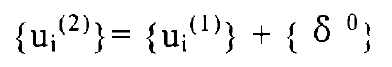
Formula satisfaction
After sorting out the relationship between:
Of which:
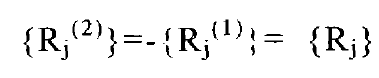
b) Free boundary
Rj=0
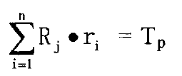
When the external torque TP is applied to Ω 1, there are:
In the calculation of multiple contact areas, if each contact point pair of Ω 1 wants to produce a rotation, there are:
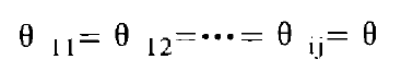
Where I = 1, 2, 3…. m, M – number of contact areas.
The displacement vector loaded by external force is related to the rotation angle of the contact node, which can be obtained by the following formula:
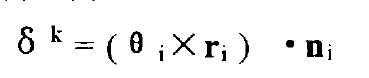
Where Ni is the unit external normal vector of the contact node.
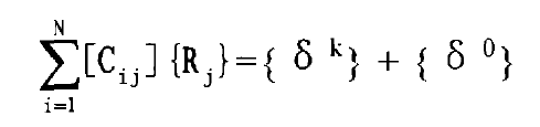
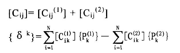
The contact equations of large and small gear tooth surfaces can be obtained by combining the formulas into matrix form:
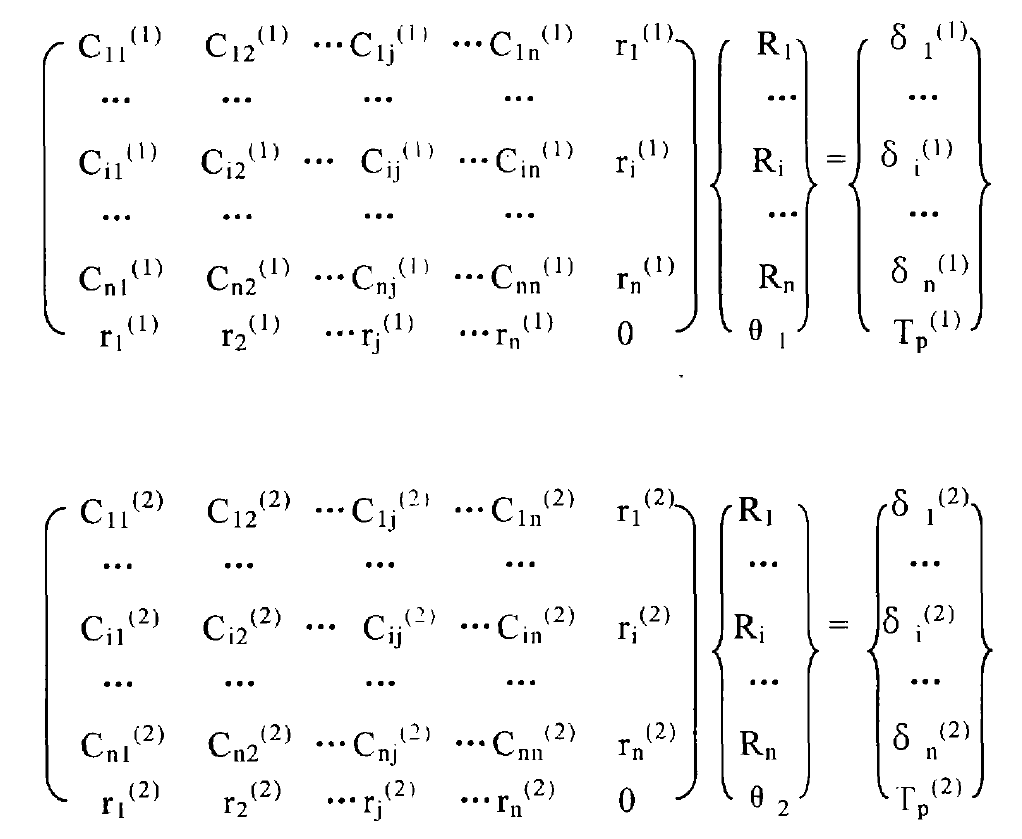
Since the contact internal forces of the contact points on the tooth surfaces of the large and small wheels are the same and the direction is opposite, it can be simplified from the above two equations:

The contact equations of all contact point pairs are formed according to the formula and solved by the Cholesky decomposition method of symmetric equations. During each iteration, the contact point pairs with the maximum negative contact internal force are eliminated according to the contact state to form a new flexibility submatrix, which is solved by cyclic iteration until all contact point pairs meet the contact condition formula and all contact internal forces are greater than or equal to zero, The contact internal force distribution of each contact area and the shape of the size of the contact area can be obtained. If the displacement and stress of each node of the contact body are required, it is only necessary to replace {RJ} solved iteratively into the equation and solve it.