
Flexible ring gear is a spur cylindrical external gear, and the ring gear after assembly deformation presents straight bus deformation along the axial direction. The assembly stress of the flexible ring gear is linear with the radial deformation along the axial direction, and the linear change rule of the assembly stress along the axial direction is clear. However, the circumferential bending stress of the flexible ring gear is non-linear due to the circumferential cross-section variation of the teeth, so it is necessary to establish a flexible ring containing actual situation.Finite element model of solid unit ring gear with tooth profile information is used to study the influence of teeth on flexure stress of flexible ring gear.
Take flexible gear teeth z1=200, modulus m=0.5 m m, top height ha=m, top clearance c=0.35m, displacement coefficient x1=3, reference tooth angle alpha 0=20o, material elastic modulus E=210 GPa, ring wall thickness h=0.7 m m, root radius r4=0.126Mm, roller position beta=25. Using the APDL language of ANSYS, the teeth are divided into sub-zonal fine mapping grids and mesh refinement is used at the flexible grooves to eliminate the influence of grid segmentation on stress. Fixed wave generator defines surface contact between the outer surface of the wave generator and the inner wall of the flexible wheel, and imposes symmetrical displacement constraints on the symmetrical surface.
Adjust the radial installation position of the roller, and through iteration calculation, the maximum radial deformation at the long axis of the flexible wheel reaches u0=m, and the circumferential stress of the flexible gear ring is shown in the figure.
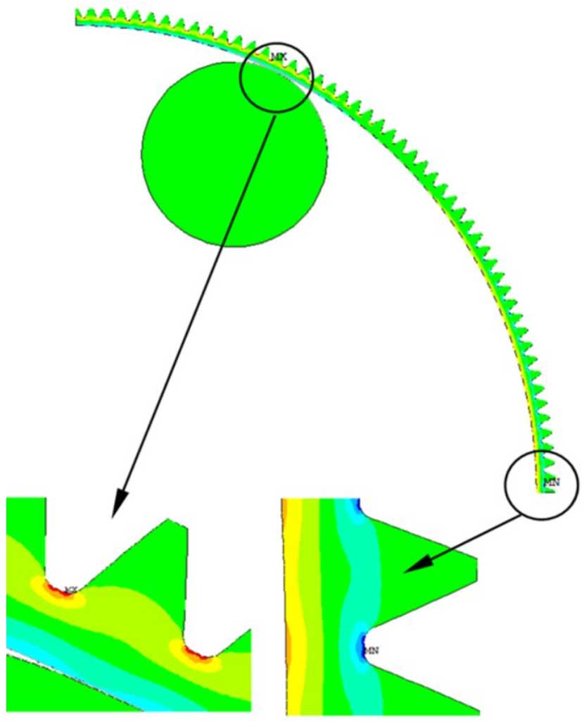
In the figure, MX is used to show the groove where the maximum circumferential tensile stress occurs at the roller position and MN is used to show the groove where the maximum circumferential compressive stress occurs at the short axle. To clearly show the maximum circumferential stress, enlarge the high stress area in the ring at the arrow. The figure shows the maximum circumferential tensile stress of the groove at the roller is 109.1.MPa, maximum circumferential pressure of the groove at the stub shaft is -115.7 MPa.