
Abstract This article focuses on the Ease – off modification of high reduction ratio hypoid gear. It begins with an introduction to the challenges and importance of hypoid gear design and manufacturing. The mathematical models of gear tooth surfaces are presented, including the tool modification of the wheel and the conjugate tooth surface equations. The topology and simulation of point – contact tooth surfaces are explored, covering the optimization of pinion processing parameters, digitization and 3D modeling of tooth surfaces, and meshing motion simulation. Dynamic performance tests, such as rolling contact quality inspection and vibration performance tests, are conducted to evaluate the performance of the modified gears. The results show that the proposed modification method improves the contact characteristics and dynamic performance of hypoid gear.
1. Introduction
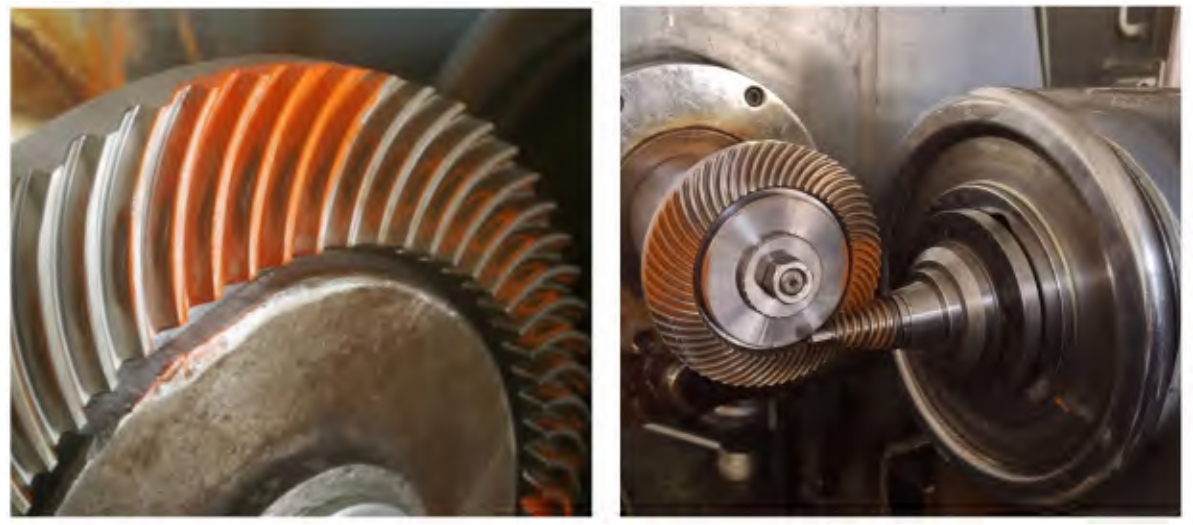
Hypoid gear is widely used in various mechanical transmission systems due to their high load – carrying capacity and smooth transmission. However, the design and manufacturing of hypoid gear, especially those with high reduction ratios, pose significant challenges. The complex spatial meshing theory and curved surface topology make it difficult to control the tooth surface design and performance accurately. In this context, the Ease – off modification method has emerged as a promising approach to optimize the performance of hypoid gear.
1.1 Challenges in Hypoid Gear Design and Manufacturing
- Complex Spatial Meshing Theory: The meshing of hypoid gear involves complex three – dimensional geometries and kinematics. The determination of correct meshing parameters requires a deep understanding of spatial geometry and kinematic principles.
- Curved Surface Topology: The tooth surfaces of hypoid gear is complex curved surfaces. The accurate description and control of these surfaces are crucial for achieving good meshing performance.
- Manufacturing Difficulties: The manufacturing process of hypoid gear requires high precision machining equipment and advanced manufacturing techniques. Any errors in the manufacturing process can significantly affect the performance of hypoid gears.
1.2 Importance of Ease – off Modification
- Improved Contact Characteristics: The Ease – off modification can adjust the curvature of the tooth surface, resulting in better point – contact characteristics. This helps to reduce edge contact and distribute the load more evenly across the tooth surface.
- Enhanced Dynamic Performance: By optimizing the tooth surface contact, the dynamic excitation during gear meshing can be reduced, leading to improved vibration and noise characteristics.
- Increased Gear Life: The more uniform load distribution and reduced dynamic stresses achieved through Ease – off modification can increase the fatigue life of hypoid gear.
2. Tooth Surface Mathematical Models
2.1 Wheel Tool Modification
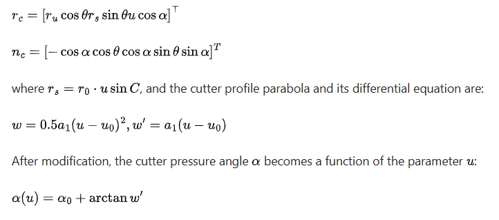
The wheel of the hypoid gear is modified using a tool (cutter or grinding wheel) with a quadratic parabola shape along a specific direction (Figure 1). The cutter surface equation in the coordinate system Sc(xc,yc,zc) is given by:
2.2 Conjugate Tooth Surface
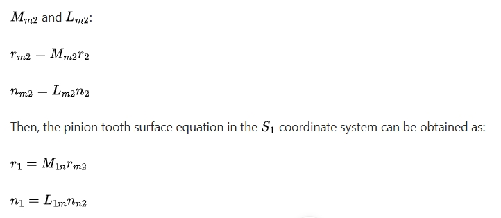
The unmodified tooth surface of the hypoid gear wheel is completely conjugate with the pinion tooth surface. Based on hypoid gear cutting principle, the pinion tooth surface generated as a conjugate of the unmodified wheel tooth surface is considered as the standard pinion. The meshing equations in different coordinate systems are used to establish the relationship between the wheel and pinion tooth surfaces. For example, if the tooth surface coordinates (radius vector and normal vector ) of the wheel are known in the coordinate system, they can be transformed to the fixed coordinate system Sm using transformation matrices and :
3. Point – Contact Tooth Surface Topology and Simulation
3.1 Pinion Processing Parameter Optimization
- Optimization Process: The optimization process involves establishing a comprehensive surface equation, solving for the pinion tooth surface processing parameters, building a 3D model of the tooth surface, analyzing the Ease – off difference surface, and obtaining tooth surface contact performance parameters such as contact path, differential curvature, and transmission error. This process is iterated until satisfactory processing parameters are obtained.
- Example Analysis: For a pair of 3:60 HRH gears, the main geometric parameters and the obtained processing parameters are shown in Tables 1 and 2 respectively.
| Parameter | Pinion | Wheel |
|---|---|---|
| Number of teeth | 3 | 60 |
| Tooth width (mm) | 28.979 | 20 |
| Midpoint helix angle (°) | 72 | 32.8983 |
| Pitch cone angle (°) | 10.9919 | 75.8605 |
| Face cone angle (°) | 10.9919 | 75.8605 |
| Root cone angle (°) | 10.9919 | 75.8605 |
| Outer diameter (mm) | 27.9074 | 145 |
| Midpoint full tooth height (mm) | 3.614 | 3.614 |
| Pitch cone vertex to intersection point distance (mm) | -5.89 | 7.43018 |
| Face cone vertex to intersection point distance (mm) | 8.68692 | 7.43018 |
| Root cone vertex to intersection point distance (mm) | -7.90658 | 4.16743 |
| Offset distance (mm) | 40 |
| Processing Parameter | Pinion | Wheel |
|---|---|---|
| Concave surface | Convex surface | |
| Tooth profile curvature parameter | 0.014 | |
| Base point position parameter (mm) | 1.4 | |
| Tool tip radius (mm) | 37.6 | 37.4 |
| Tool pressure angle (°) | 20.5 | 19.0 |
| Radial tool position (mm) | 51.9712 | 53.1513 |
| Angular tool position (°) | 75.5564 | 42.2143 |
| Axial wheel position (mm) | -0.2667 | 5.3428 |
| Vertical wheel position | 39.9843 | |
| Wheel blank installation angle (°) | 10.9919 | 74.7639 |
| Bed position (mm) | -1.525318 | |
| Roll ratio | 19.9492 |
3.2 Tooth Surface Digitization and 3D Modeling
- Calculation of Tooth Surface Data: Using software like Matlab, the tooth surface data of the hypoid gear is calculated based on the established meshing relationships and coordinate systems. The tooth surface grids of the wheel and pinion are typically set to a certain number of rows and columns (e.g., 13 rows and 47 columns).
- 3D Model Construction: The calculated tooth surface data points are imported into 3D software such as UG to create the 3D models of the wheel and pinion. The 3D models can visually show the differences in tooth shape and curvature before and after modification. For example, the standard pinion has a thicker tooth and smaller tooth profile curvature, while the modified pinion has a narrower tooth top and larger tooth profile curvature.
3.3 Tooth Surface Meshing Motion Simulation
- Model Assembly and Setup: The generated 3D gear models are assembled according to the preset installation distance. The normal distance between the wheel and pinion tooth surfaces is set to a specific value (e.g., -0.00635 mm). Different colors are assigned to the models for better visualization, and the pinion is set to a semi – transparent state.
- Simulation Results: In the UG motion module, by setting parameters such as links, motion pairs, and gear coupling pairs, the contact state of the tooth surfaces during simulated rolling inspection can be observed. It is found that for a 3:60 HRH gear, 5 pairs of teeth are in contact simultaneously, indicating an overlap coefficient of 5. The contact area of the conjugate tooth surface is large with severe edge contact at the tooth top and root, while the modified tooth surface has an elliptical instantaneous contact area with the edge contact removed at the tooth top and root.
4. Dynamic Performance Tests
4.1 Rolling Contact Quality Inspection
- Gear Machining and Testing: The HRH gears with the specified parameters are machined and then tested on a Y9550 type rolling inspection machine. Red lead powder is evenly applied to the tooth surfaces.
- Contact Spot Analysis: The contact spots formed on the tooth surfaces after rolling inspection show that the convex surface contact area of the wheel is located in the middle of the tooth surface near the small end, without edge contact. The size and position of the contact spots are ideal and are generally consistent with the contact spots obtained from the motion simulation, verifying the correctness of the modification method and simulation results.
4.2 Vibration Performance Tests
- Test Setup: A test bench is set up consisting of a drive motor, torque sensor, HRH gearbox, and magnetic powder loader. Torque sensors are connected to the input and output ends of the gearbox to measure speed, torque, and power. The vibration acceleration signals of 1 (vertical x), 2 (axial z), and 3 (horizontal y) channels can be monitored during the operation of the HRH reducer.
- Test Results and Analysis:
- Vibration Spectrum at Different Loads: At an input speed of 1410 r/min and different wheel loads (50 N·m and 200 N·m), the vibration acceleration amplitude – frequency characteristics of each channel are analyzed. The hypoid gear meshing frequency and its multiples are clearly visible in all three channels, along with the shaft frequency signals, indicating the presence of tooth pitch errors or shaft misalignment. The vibration acceleration amplitude is largest at the 2nd harmonic of the meshing frequency.
- Effect of Load on Vibration: Comparing the two load conditions, it is found that as the load increases, the vibration amplitude decreases. This is because the tooth stiffness and actual overlap degree increase with the load, reducing the dynamic excitation of the teeth.
- Effect of Speed on Vibration: Analyzing the vertical channel vibration acceleration amplitude at different speeds and loads shows that as the speed increases, the hypoid gear vibration acceleration harmonic intensity increases. The strongest vibration signal band is between 100 – 200 Hz, where the meshing main frequencies of all three speeds are located, indicating that the natural frequency has a significant impact on the vibration amplitude.
5. Conclusions
Considerations for Design: In the design of hypoid gear, especially those with a small number of teeth, the potential for shaft frequency modulation with the main frequency due to low safety margins should be considered. Overall, the research provides valuable insights and methods for the design and manufacturing of high – quality hypoid gear.
Improved Contact and Performance: The proposed method of wheel tool modification and pinion general hobbing for hypoid gear effectively addresses the issues of insufficient wheel tooth profile curvature and high twist of the pinion tooth surface. The Ease – off modification achieves point – contact tooth surfaces, improving the contact characteristics and dynamic performance of hypoid gear.
Validated by Tests: The 3D motion simulation and dynamic performance tests confirm the effectiveness of the modification method. The contact area of the modified tooth surface is consistent with the actual contact spots, and the vibration performance tests show that hypoid gear has good meshing transmission performance and stable meshing quality.