
The finite element mesh generation of contact is realized. In order to obtain more accurate contact stress of gear teeth, enough mesh density must be selected. The solid 45 element is selected to map the end face of the gear, and then the surface mesh is swept along the helical line of the gear to generate the finite element mesh of the whole gear tooth. 28406 elements and 63220 nodes are obtained.
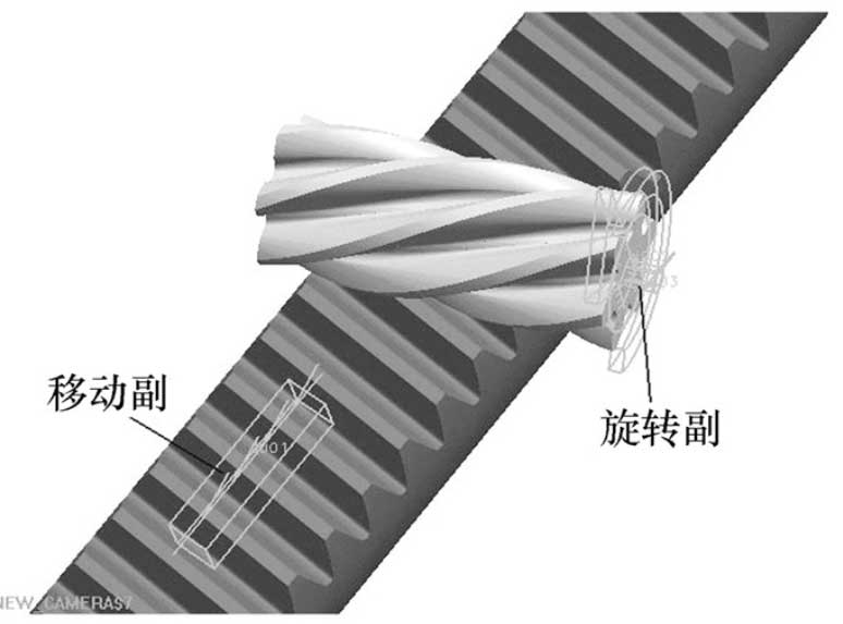
It is defined that the material of pinion is 16MnCr5 carburizing and quenching, the hardness of tooth surface is 56-62hrc, and that of gear rack is 45 steel after quenching and tempering, the hardness of tooth surface is 50HRC. It is defined that the pinion tooth surface is the contact surface, the gear rack tooth surface is the target surface, the mesh surface is the soft body soft body contact analysis, and the two contact bodies have approximate stiffness. When creating contact pairs, ANSYS can automatically ensure that the external normal direction of the contact element is face-to-face. The degree of freedom relationship between two contact bodies is analyzed, and the boundary conditions of contact are determined. The gear rack constraint is applied so that the gear has only the degree of freedom of rotation around its axis of rotation, and the gear rack has only the degree of freedom of movement along its axis. Select all nodes on the pinion gear teeth and apply the torque T to rotate around its rotation center axis as follows:
T=Ftd1/2 (4)
Where: D1 is the diameter of gear graduation circle.
Solve and view the results. The contact stress nephogram of gear is as shown in the figure. As shown in the figure, the maximum contact stress point appears near the contact line, and the maximum contact stress is 1556.4mpa.
The traditional calculation formula of contact stress σ h is:
σΗ=ΖΗΖEΚFtbd1εαu±1u (5)
Where, K is the load coefficient, Zh is the area coefficient, Ze is the elastic influence coefficient, u is the ratio of teeth, B is the tooth width, and ε α is the coincidence degree of the gear end face.
The parameters are selected according to the gear parameters and working conditions, among which, k = 1.4; zh = 2.1; Ze = 189.8; u →∞ (the gear rack can be regarded as infinite gear, so the ratio of teeth is infinite); b = D1 = 12.528mm; ε α = 1.65; substituting (5), the maximum contact stress of the tooth surface is 1643.48mpa.
It can be seen from the comparison that the contact stress of the tooth surface calculated by the traditional method is too large. This is because the traditional gear contact stress calculation is based on the line contact calculation, in fact, the gear teeth are local area contact. Therefore, the contact analysis of gear and rack based on the accurate finite element model is more accurate.