
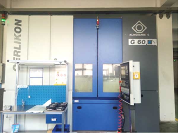
My research focuses on the motion control methodology and supporting software development for a new generation of domestic, fully Computer Numerical Control (CNC) vertical spiral bevel gear milling machines. Traditional horizontal CNC gear milling machines have limitations regarding rigidity and chip flow during high-speed dry cutting. The vertical configuration, where the tool spindle is mounted on a vertical column and the workpiece spindle is perpendicular to the horizontal plane, offers inherent structural advantages. This research derives the fundamental kinematic principles for both cutting and on-machine measurement specific to this vertical structure, develops the corresponding control algorithms, and implements them within a user-friendly CNC software suite to enable closed-loop manufacturing.
The development of spiral bevel gear manufacturing technology has been significantly driven by advances in both theory and equipment. Internationally, companies like Gleason and Klingelnberg have established comprehensive “expert systems” for digital integrated manufacturing. While domestic research on gear milling theory, particularly concerning the “Gleason system,” has made substantial progress since the late 20th century, there remains a gap in the integration of advanced machine tools with sophisticated, proprietary software. Modern production demands a closed-loop process of cutting, measuring, compensating, and re-cutting on a single platform to eliminate errors from re-fixturing. This work aims to contribute to establishing such a capability for domestic vertical gear milling machines.
Kinematic Modeling for Gear Milling on a Vertical Machine
The core of gear milling lies in precisely controlling the relative motion between the cutter (tool) and the gear blank (workpiece). The first step is to establish the basic machine tool model based on traditional mechanical milling machine principles, defining the relative position and motion during generation. For a face-milling process with a cutter tilt, the key vectors include the cutter axis, workpiece axis, and the vector from the workpiece pivot to the cutter center.
Let $$ \Sigma_s = [O_s; i_s, j_s, k_s] $$ be the static machine coordinate system. The cutter axis vector in the generation coordinate system is derived from the basic machine settings like cutter tilt $$ i_0 $$, swivel angle $$ j_0 $$, and cradle angle $$ q_t $$:
$$ \mathbf{V_c} = \mathbf{M}(-\mathbf{k}, q_t) \mathbf{M}(\mathbf{j}, j_0) \mathbf{M}(\mathbf{i}, i_0) \mathbf{k} $$
The vector from the workpiece pivot to the cutter center, incorporating settings like sliding base $$ X_b $$, workpiece offset $$ E_m $$, and machine root angle $$ \Gamma $$, is:
$$ \mathbf{V_l} = X_p \mathbf{V_p} – X_b \mathbf{k} + E_m \mathbf{j} + S \mathbf{V_{qt}} $$
where $$ \mathbf{V_p} = [\cos(\Gamma), 0, \sin(\Gamma)] $$ is the workpiece axis and $$ \mathbf{V_{qt}} = [\cos(q_t), -\sin(q_t), 0] $$.
The transformation to the vertical machine tool structure requires two rotations to align the cutter axis with the vertical Z-axis of the new machine. The required rotation angles, $$ dA $$ and $$ dB $$, are calculated from the components of $$ \mathbf{V_c} $$ and $$ \mathbf{V_p} $$. Finally, the axis coordinates (X, Y, Z, A, B) for the 5-axis vertical gear milling machine are obtained as functions of the traditional machine settings and the cradle angle:
$$ \begin{cases}
X = f_X = -\mathbf{V_{ls}} \cdot \mathbf{i_s} \\
Y = f_Y = \mathbf{V_{ls}} \cdot \mathbf{j_s} \\
Z = f_Z = -\mathbf{V_{ls}} \cdot \mathbf{k_s} + R_d + C_t \\
A = f_A = Ra \cdot q – q_s – dA \\
B = f_B = \Gamma + dB
\end{cases} $$
Here, $$ Ra $$ is the ratio of roll, $$ q_s $$ is the start cradle angle, $$ R_d $$ is the mounting distance, and $$ C_t $$ is the fixture length. This model allows the CNC system to replicate any traditional gear milling motion through coordinated 5-axis interpolation.
To generate the theoretical tooth surface, the conjugate contact points between the cutter head and the workpiece are calculated using the equation of meshing. For a point on the cutter blade with a normal vector $$ \mathbf{n_0} $$ in the cutter coordinate system, its position and normal are transformed into the static system. The condition for contact is that the relative velocity at the point is perpendicular to the common normal:
$$ \mathbf{v_{12}} \cdot \mathbf{n_s} = 0 $$
where $$ \mathbf{v_{12}} = \mathbf{v_e} – \boldsymbol{\omega_1} \times \mathbf{V_{as}} – \boldsymbol{\omega_2} \times \mathbf{V_{as}} $$. Solving this equation yields the parameters defining the conjugate contact line, which, when swept according to the machine kinematics, defines the theoretical tooth surface $$ \mathbf{R} $$ as a function of machine settings, tool parameters, and motion parameters $$ (q_t, \theta_t) $$.
| Machine Setting / Axis | Symbol | Role in Vertical Machine Kinematics |
|---|---|---|
| Radial Setting | S | Integrated into X, Y axis interpolation (part of $$ \mathbf{V_{ls}} $$). |
| Work Offset (Horizontal) | $$ X_p $$ | Integrated into X, Y axis interpolation (part of $$ \mathbf{V_{ls}} $$). |
| Sliding Base | $$ X_b $$ | Integrated into Z-axis position. |
| Work Offset (Vertical) | $$ E_m $$ | Integrated into X, Y axis interpolation (part of $$ \mathbf{V_{ls}} $$). |
| Machine Root Angle | $$ \Gamma $$ | Directly sets B-axis angle, with correction $$ dB $$. |
| Cradle Rotation | $$ q_t $$ | Drives A-axis rotation via ratio-of-roll, with offset $$ dA $$. |
On-Machine Measurement and Error Compensation
Integrating a touch-trigger probe onto the vertical gear milling machine enables closed-loop manufacturing. The measurement model establishes the relationship between the probe center $$ \mathbf{V_m} $$, the cutter center $$ \mathbf{V_c} $$, and the machine coordinate system: $$ \mathbf{V_m} = \mathbf{V_c} + \mathbf{V_{cm}} $$, where $$ \mathbf{V_{cm}} $$ is determined through a calibration routine using a master ring gauge.
For pitch deviation measurement, the probe contacts a designated point (e.g., the midpoint of the tooth flank) on each tooth. The sequence of recorded A-axis angles reveals the angular spacing between teeth. Pitch errors are quantified as:
$$ \Delta f_{pt}(i) = \theta_A(i) – \frac{2\pi}{n} \cdot i $$
$$ f_{pt} = \max(|\Delta f_{pt}(i)|) – \min(|\Delta f_{pt}(i)|) $$
$$ F_p = \max(\Delta f_{pt}(i)) – \min(\Delta f_{pt}(i)) $$
where $$ n $$ is the number of teeth.
For profile deviation measurement, a grid of points is defined over the tooth flank. The probe path is planned by offsetting each theoretical point along its normal vector $$ \mathbf{n} $$ to create an approach point $$ \mathbf{R_I} = \mathbf{R} + \delta \cdot \mathbf{n} $$ and a target point beyond the surface. The machine moves the probe from $$ \mathbf{R_I} $$ toward the target, triggering upon contact. The actual contacted point $$ \mathbf{R_g} $$ is calculated from the triggered machine coordinates, probe radius compensation, and inverse coordinate transformations. The profile deviation $$ \delta $$ at a point is the distance between $$ \mathbf{R_g} $$ and the theoretical surface along the normal:
$$ \delta = (\mathbf{R_g} – \mathbf{R}(u,v)) \cdot \mathbf{n}(u,v) $$
Software Development for Integrated Control
The developed software, tailored for the Siemens 840Dsl CNC system, acts as the central hub for gear milling operations. Its architecture integrates several key modules communicating via Siemens’ provided C++ API (e.g., DataSvc for accessing NC/PLC variables).
The core functionality is built around a dynamic-link library (DLL) containing the main algorithms. The workflow is as follows: The user inputs gear parameters, machine settings, tool data, and measurement plans through dedicated MFC-based graphical interfaces. This data is passed to the algorithm DLL. For gear milling, the algorithm computes the tool path (X, Y, Z, A, B coordinates) and generates the corresponding NC code, which is loaded into the CNC system. For measurement, it generates the probe scanning NC cycle. During execution, the software’s monitoring module reads real-time axis positions, spindle data, and system alarms via the API, displaying them on the main interface. After measurement, acquired point data is processed by the error analysis module to calculate and graphically display pitch and profile deviations.
The most advanced module handles error compensation. The measured profile deviations $$ \delta_i $$ across the tooth grid are modeled as an error surface. This surface is approximated near the design contact point by a local polynomial expansion in a local coordinate system (X: lengthwise, Y: profile direction):
$$ h(X,Y) = c_1 + c_2X + c_3Y + c_4X^2 + c_5XY + c_6Y^2 + … $$
The coefficients $$ c_j $$ represent specific geometric deviations: $$ c_1 $$ (offset), $$ c_2, c_3 $$ (slope errors affecting spiral angle and pressure angle), $$ c_4, c_5, c_6 $$ (curvature errors related to crowning and twist). The goal of compensation is to adjust the original machine settings $$ \mathbf{x} $$ by a delta $$ \Delta \mathbf{x} $$ so that the theoretical tooth surface produced with the new settings $$ \mathbf{x} + \Delta \mathbf{x} $$ minimizes the difference between its deviation surface coefficients and those from the measured error surface. This is formulated as a nonlinear least-squares optimization problem, with an added term to control root cone geometry:
$$ \min_{\Delta \mathbf{x}} F(\Delta \mathbf{x}) = \frac{1}{2} \sum_{j=1}^{m+k} \omega_j [r_j(\Delta \mathbf{x})]^2 $$
$$ r_j(\Delta \mathbf{x}) = c’_j(\Delta \mathbf{x}) – c_j, \quad \text{for } j=1,…,m $$
$$ r_{m+ l}(\Delta \mathbf{x}) = \Delta \delta_{f,l}(\Delta \mathbf{x}) \quad \text{(root cone error constraints)} $$
The solution $$ \Delta \mathbf{x} $$ provides the corrective adjustments for the next gear milling trial.
Simulation and Experimental Verification
The correctness of the gear milling and measurement algorithms was first verified through simulation. A virtual model of the vertical 5-axis machine was constructed. Using the parameters for a sample gear pair (7/43 ratio), the software generated the NC code for machining. This code was executed in the simulator to successfully machine virtual gear blanks. Subsequently, the on-machine measurement NC code was run on the simulated machined gears. The measured deviations were on the sub-micron scale, confirming the algorithmic accuracy considering model discretization errors.
| Gear | Flank | Max Profile Error Before Compensation (µm) | Max Profile Error After Compensation (µm) |
|---|---|---|---|
| Pinion | Convex | 10.0 | 8.2 |
| Pinion | Concave | 20.8 | 7.5 |
| Gear | Concave | 26.6 | 12.5 |
The error compensation algorithm was tested experimentally using existing horizontal gear milling and measuring equipment. A gear pair was machined, measured on a gear measuring center, and the data was input into the compensation software. The calculated corrective machine settings were applied to machine a new gear pair. The table above shows a significant reduction in profile errors after compensation. Furthermore, the contact pattern of the compensated gears on a rolling tester showed excellent agreement with the theoretical pattern, validating the effectiveness of the compensation strategy.
Conclusion and Outlook
This research has established a complete coordinate control methodology for fully CNC vertical spiral bevel gear milling machines, encompassing gear milling kinematics, on-machine measurement, and error compensation. The developed software successfully integrates these functions, providing a practical platform for closed-loop precision manufacturing. The simulation and experimental results confirm the validity of the proposed models and algorithms. Future work will focus on the in-depth commissioning of all software functions on the physical vertical gear milling prototype, the integration of the compensation algorithm directly into the software’s C++ codebase, and the exploration of adapting this control methodology to domestic CNC systems to further advance the localization of high-end gear milling technology.