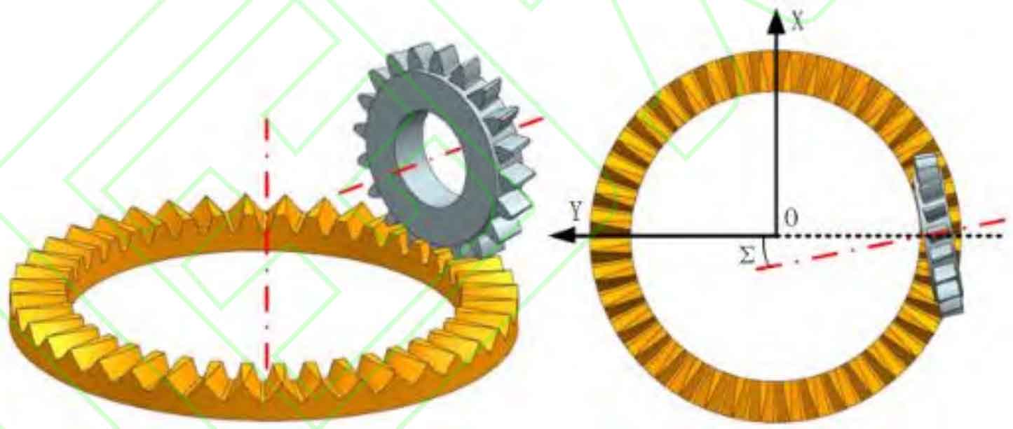
Bevel gear turning gear can be regarded as the combination of hobbing and shaper. In the machining process, the tool and workpiece rotate at high speed around the central axis at the same time. At the same time, the cutter moves along the radial direction of the workpiece (Y direction in Figure 1) and cuts off the workpiece layer by layer. When the cutter translates from the outer circle to the inner circle of the workpiece, the machining of the whole bevel gear can be completed.
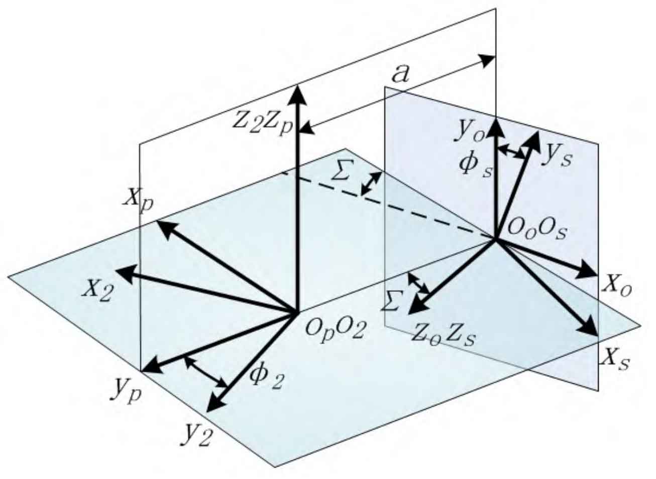
Machining coordinate system (Figure 2). In the process of bevel gear turning, the workpiece rotates around the 𝑍 axis, and SP (OP − xpypzp) is the spatial fixed coordinate system of the workpiece, which coincides with the initial position of the workpiece. During machining, the tool rotates around the 𝑍 axis and feeds in the 𝑌 direction. The distance between 𝑍 and 𝑌 is a, and a gradually decreases with the progress of processing. What is the angle between 𝑌 and 𝑍 Σ。 Due to the existence of this angle, the cutting force will be generated between the tool and the workpiece in the machining process to cut off the material.
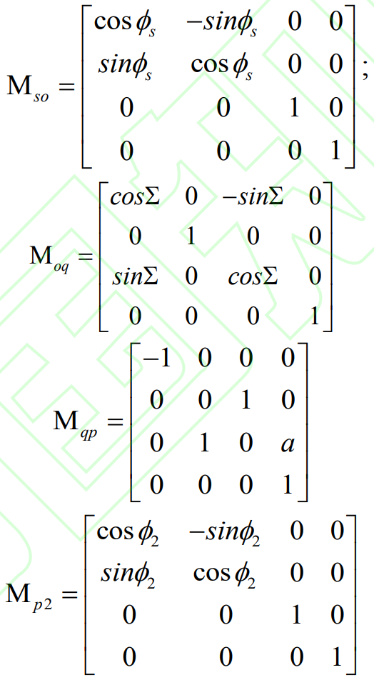
According to the principle of spatial coordinate transformation, the transformation relationship between workpiece coordinate system 𝑆 2 and gear turning tool coordinate system 𝑆 can be expressed as:
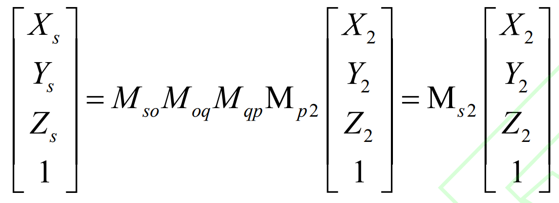
In the formula,