The machining of spur gears can be modeled on the machining method of cylindrical gears, based on the principle of generation, using tools that have the same or similar parameters as the cylindrical gears meshing with spur gears. According to the generating principle, the straight tooth surface gear is processed. According to the given transmission ratio, the cutter tooth surface of the straight tooth surface gear rotates relative to the straight tooth surface gear, and the cutter envelope surface of the gear shaping cutter processes the tooth surface of the straight tooth surface gear. Therefore, the tooth surface equation of a spur gear is derived from the tooth surface equation of a gear shaping cutter based on the meshing principle.
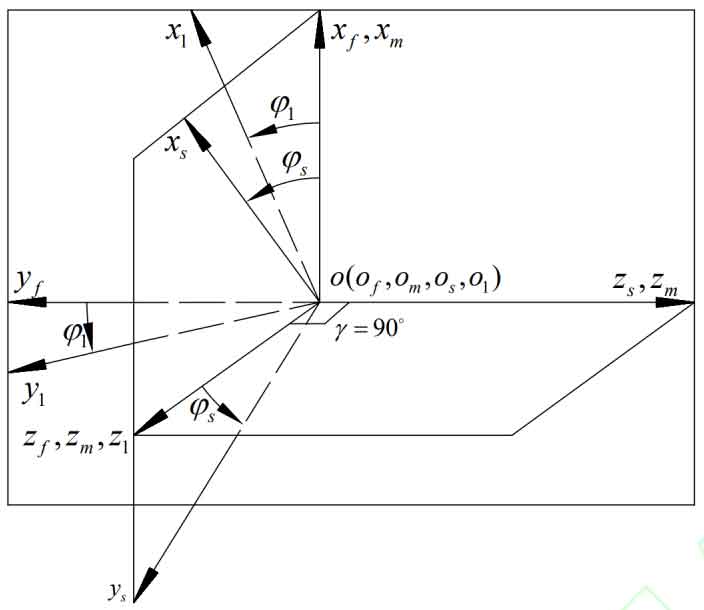
The machining coordinate system of spur gear is shown in the figure, where the fixed coordinate systems of cutter M and spur gear 1 at their initial positions are Sm-Om xm ym zm and Sf-Of xf yf zf, respectively. The coordinate systems of cutter Nm and spur gear N1 rotating simultaneously are Ss-Os xs ys zs and S1-O1 x1 y1 z1, respectively. φ S and φ 1 is the angle at which the cutter N m and the spur gear N1 rotate around the rotation axes zm and z1, ω s , ω 1 is the angular velocity of the tool rotation and the angular velocity of the machined spur gear rotation.
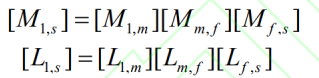
According to the transmission relationship, the coordinate system for machining spur gear can be derived from the cutter coordinate system to the face gear coordinate system, as shown in the figure. The conversion matrices [M1, s] and [L1, s] can be derived, where: