Abstract
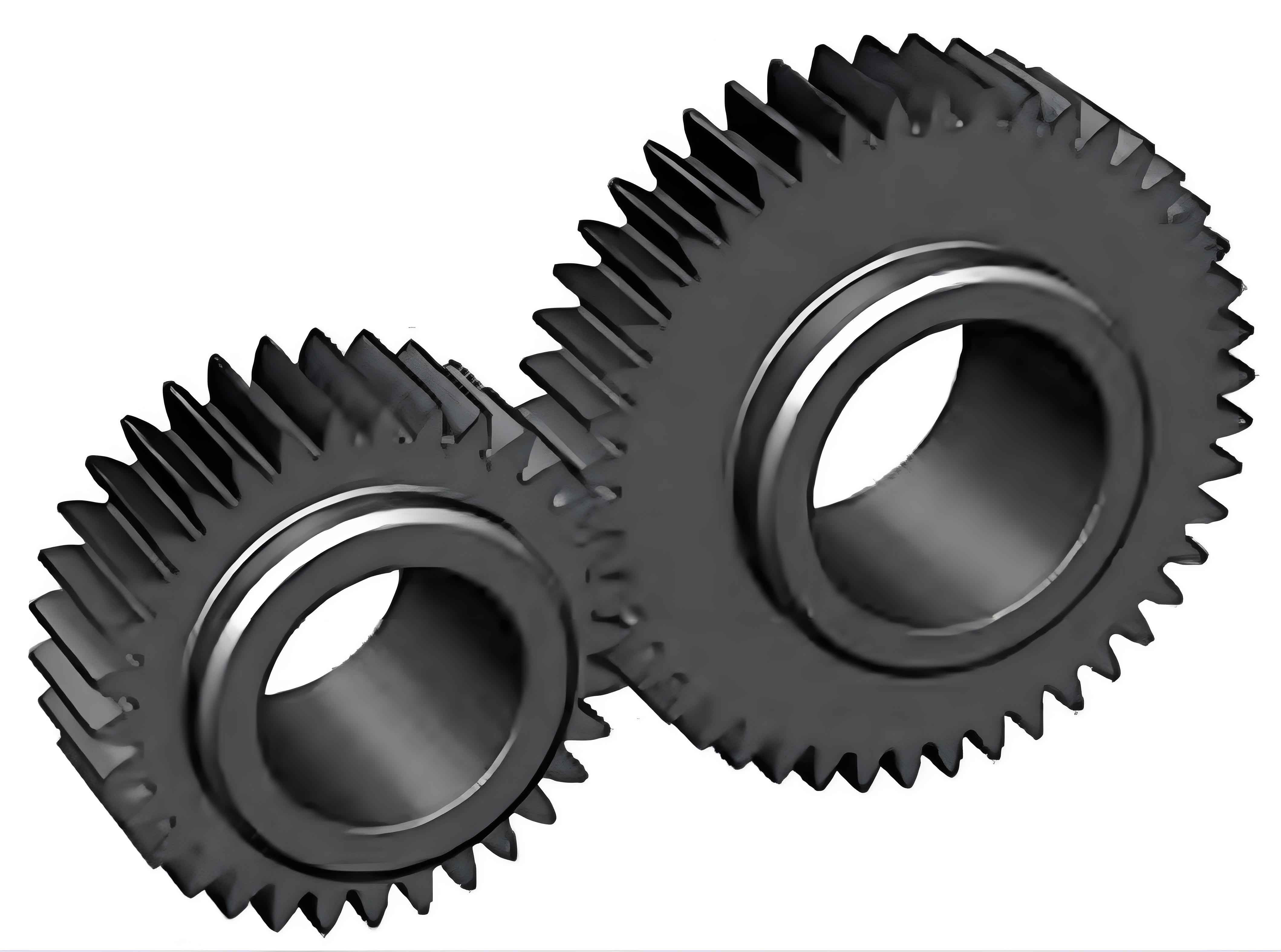
Gears are widely used in aerospace, automotive, and energy fields. Failures of spur gear can result in economic losses and significant safety accidents. This paper focuses on the crack propagation analysis and fatigue life prediction of spur gear tooth roots.

1. Introduction
The uneven distribution of load on spur gear teeth during actual meshing necessitates a thorough understanding of tooth root crack propagation and fatigue life. This paper aims to analyze crack propagation and predict fatigue life in spur gear tooth roots.
2. Crack Propagation and Fatigue Life Fundamentals
2.1 Crack Formation Mechanism and Classification
| Crack Type | Description |
|---|---|
| Type I (Opening Mode) | Crack opens and closes perpendicular to the load |
| Type II (Sliding Mode) | Crack slides parallel to the load |
| Type III (Tearing Mode) | Crack tears out of the plane of the material |
2.2 Stress Intensity Factor (SIF)
The SIF is a critical parameter in fatigue fracture studies. It is used to describe the stress field near the crack tip.
2.3 Crack Propagation Life
The Paris formula is a classic model for estimating crack propagation life:
where is the crack growth rate, ΔK is the stress intensity factor range, C and n are material constants.
3. Parameterized Modeling of Spur Gear
ANSYS APDL is used for parameterized modeling of spur gear. The following table lists some key gear parameters:
| Parameter | Symbol | Value |
|---|---|---|
| Modulus | M | 4.5 |
| Number of Teeth | Z | 39 |
| Pressure Angle | Alfa | 20° |
| Addendum Coefficient | Ha | 1 |
| Clearance Coefficient | C | 0.25 |
4. Crack Propagation Analysis
4.1 Simulation Process
The simulation process involves several steps:
- Model Preparation: Create a spur gear model using ANSYS.
- Crack Embedding: Embed an initial crack using FRANC3D.
- Load Application: Apply loads and constraints.
- Crack Propagation Simulation: Simulate crack propagation using FRANC3D and ANSYS.
4.2 Crack Propagation Results
| Load Condition | Crack Propagation Path | Stress Intensity Factor Variation |
|---|---|---|
| Uniform Load | Straight path | Smooth variation |
| Actual Load | Tortuous path | Fluctuating variation |
5. Fatigue Life Prediction
5.1 Crack Growth Rate
The crack growth rate under different loads is compared:
| Load Condition | Longitudinal Crack Growth Rate | Transverse Crack Growth Rate |
|---|---|---|
| Uniform Load | Slower | – |
| Actual Load | Faster | – |
5.2 Fatigue Life Prediction Results
The fatigue life is predicted using the Paris formula. The results show that uneven load distribution reduces gear fatigue life.
6. Effect of Initial Crack Position on Gear Fatigue Life
The initial crack position is rotated around the Z-axis by different angles (15°, 30°, 45°, 60°). The crack expansion life is predicted for each case.
Conclusion
This paper presents a comprehensive analysis of crack propagation and fatigue life prediction in spur gear tooth roots. The results provide insights into the effects of load distribution and initial crack position on crack propagation behavior and fatigue life. The proposed methods can be used for early detection and prevention of spur gear failures.
