
I have focused my recent research and process development on the manufacturing route for the automotive rear axle pinion gear, because this pinion gear is one of the most heavily loaded and geometrically critical components in the vehicle power transmission system. The pinion gear transmits torque from the driveshaft to the ring gear, and its working conditions involve repeated bending, contact fatigue, torsional loading, and impact. For this reason, the pinion gear must be produced with a sound internal structure, accurate dimensions, and a stable material flow pattern. In my work, I propose a “cross wedge rolling plus die forging” route for the pinion gear instead of the conventional “hammer drawing plus die forging” route. The conventional process for the pinion gear has low production efficiency, low material utilization, high equipment tonnage, many hammer blows, and poor dimensional accuracy. The new route uses cross wedge rolling, often abbreviated as CWR, to prepare the pinion gear billet, and then uses die forging to finish the pinion gear. This paper presents my analysis of the pinion gear billet, the structural optimization of the pinion gear, the rotation condition of the workpiece during CWR, the effect of groove shape on the die side wedge surface, and the influence of process parameters on the central damage value of the pinion gear.
I begin with the key motivation. The rear axle pinion gear has a large demand volume in the automotive industry. Any improvement in the manufacturing process of the pinion gear can reduce cost, shorten the production cycle, and improve the quality of the final pinion gear. The traditional process for the pinion gear is based on hammer drawing followed by die forging on a forging press. In that route, the billet is first drawn out on a hammer, and then the pinion gear is formed by die forging. The process requires high-tonnage equipment, many blows, low production efficiency, poor dimensional accuracy, and low material utilization. Therefore, I investigated a cross wedge rolling process for the pinion gear billet. Cross wedge rolling is an advanced forming technology for shafts and axisymmetric parts. It has been studied for large shafts, hollow parts, alloy shafts, aluminum alloy shafts, high-carbon steel rods, high-speed railway axle steel, and connecting rod billets. However, the application of cross wedge rolling to the rear axle pinion gear still requires special attention to rotation stability, die universality, and central damage. My objective is to produce a pinion gear billet by CWR, then complete the pinion gear by die forging, and finally improve the production efficiency and product quality of the pinion gear.
Table 1 summarizes the main comparison between the conventional process and the proposed process for the pinion gear. The table is expressed in a general way, because the exact values depend on the pinion gear size and the available equipment. Nevertheless, the trend is clear: the proposed route reduces the number of operations, improves material utilization, and makes the pinion gear billet more suitable for automated production.
| Item | Conventional route for pinion gear | Proposed route for pinion gear |
|---|---|---|
| Main operations | Hammer drawing and die forging | Cross wedge rolling and die forging |
| Equipment load | High tonnage, many blows | Lower tonnage, continuous rolling |
| Production efficiency | Low | High |
| Material utilization | Low | Higher |
| Dimensional accuracy | Poor | Better |
| Die universality for pinion gear | Limited | Improved by structural optimization |
| Internal quality control | Difficult | Can be controlled through process parameters |
The structural optimization of the pinion gear is the first step in my method. Rear axle pinion gears have many types, and the position and size of the rod step are different for each pinion gear type. If I attempt to form every pinion gear by one cross wedge rolling pass, then every pinion gear type would require a dedicated CWR die. The manufacturing cost of a CWR die is high, especially for trial production or small-batch production. Therefore, I optimized the pinion gear structure by canceling the rod step and replacing the rod with a tapered shape. I selected many types of pinion gear and optimized them together. The rod inclination angle of the pinion gear ranged from about 1° to about 3°. To include more pinion gear types and reduce cost, I selected a rolled billet with a rod inclination angle of about 2°. After rolling, the pinion gear is formed by die forging. This approach enables the universalization of the CWR die for the pinion gear billet to a certain extent.
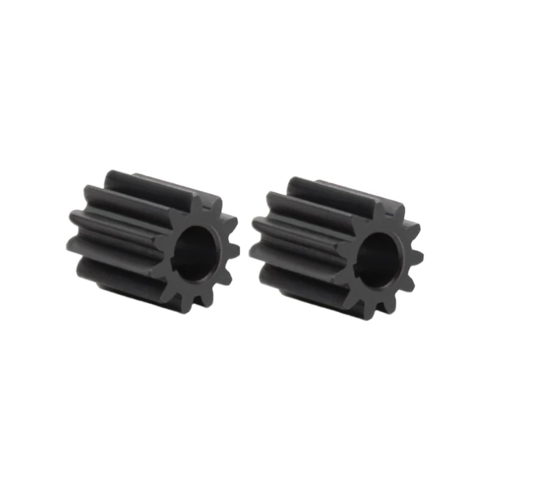
The geometric definition of the tapered rod for the pinion gear can be written as follows. Let the rod length be \(L\), the large-end diameter be \(D_1\), and the small-end diameter be \(D_2\). The inclination angle \(\theta\) of the pinion gear rod is defined by:
$$ \theta = \arctan\left(\frac{D_1 – D_2}{2L}\right) $$
For the selected pinion gear family, I set \(\theta \approx 2^\circ\). The diameter reduction along the rod is therefore gradual. This gradual reduction is important for the pinion gear because it avoids a sharp step that would otherwise prevent the same CWR die from being used for multiple pinion gear variants. The optimized shape also maintains sufficient machining allowance on each step of the pinion gear after die forging. In other words, the pinion gear is rolled as a tapered billet, and the final pinion gear geometry is produced by die forging with a small amount of excess material. The pinion gear therefore benefits from both the high productivity of CWR and the shape precision of die forging.
The cross wedge rolling process for the pinion gear billet is based on a pair of wedge tools that move relative to the workpiece. The workpiece is a round bar, and the wedge tools reduce its diameter while elongating it. The main process parameters for the pinion gear are the forming angle \(\alpha\), the widening angle \(\beta\), and the area reduction \(Z\). The area reduction for the pinion gear is defined as:
$$ Z = \frac{A_0 – A_1}{A_0} \times 100\% $$
where \(A_0\) is the initial cross-sectional area of the pinion gear billet and \(A_1\) is the final cross-sectional area of the rolled pinion gear billet. For a circular cross section:
$$ A_0 = \frac{\pi}{4} D_0^2 $$
$$ A_1 = \frac{\pi}{4} D_1^2 $$
Therefore, the area reduction for the pinion gear can also be written as:
$$ Z = 1 – \left(\frac{D_1}{D_0}\right)^2 $$
For my pinion gear study, the initial billet diameter was \(D_0 = \Phi 50\) mm. The area reduction was \(Z = 64.4\%\). Thus, the final diameter of the rolled pinion gear section is:
$$ D_1 = D_0 \sqrt{1 – Z} $$
$$ D_1 = 50 \sqrt{1 – 0.644} \approx 29.8 \text{ mm} $$
This value shows that the pinion gear billet undergoes a substantial diameter reduction during CWR. The large reduction is beneficial for material savings, but it also increases the risk of central damage in the pinion gear. Therefore, the process parameters must be selected carefully.
The forming angle \(\alpha\) and the widening angle \(\beta\) control the geometry of the wedge tool and the metal flow in the pinion gear. The widening angle is related to the axial feed of the wedge. If the roll radius is \(R\) and the angular velocity is \(\omega\), then the widening velocity \(v_b\) of the wedge relative to the pinion gear can be approximated by:
$$ v_b = \omega R \tan\beta $$
where
$$ \omega = 2\pi n $$
and \(n\) is the rotation speed of the roll in revolutions per second. In my simulation, I used \(n = 0.8\) rad·s\(^{-1}\), which is an angular velocity rather than a revolution frequency, so the relation above is written in terms of angular speed. The wedge advances in the axial direction of the pinion gear as the roll rotates. A larger widening angle increases the axial feed per revolution and shortens the rolling time. However, a larger widening angle also increases the tendency for axial metal flow and can increase the central damage of the pinion gear. A smaller widening angle gives more rotation cycles and more rubbing, which may improve the roundness of the pinion gear but reduces productivity. Therefore, the widening angle for the pinion gear must balance productivity and internal quality.
The forming angle \(\alpha\) controls the slope of the wedge in the radial direction. A larger forming angle makes axial metal flow more difficult, so more metal flows in the radial and tangential directions. This can increase the non-uniformity of deformation in the pinion gear and produce larger tensile stresses in the center. A smaller forming angle makes axial flow easier, but it also increases the contact length and the rolling force. For the pinion gear, I first used \(\alpha = 25^\circ\). Later, to increase the area of the side wedge surface for slotting, I changed the forming angle to \(\alpha = 15^\circ\). For production validation, I used \(\alpha = 16.5^\circ\). These changes are part of my iterative design for the pinion gear.
I used rigid-plastic finite element method to simulate the cross wedge rolling of the pinion gear billet. The dies were treated as rigid bodies, and the workpiece was treated as a plastic body. The material of the pinion gear was 20CrMnTiH steel. The workpiece was meshed with tetrahedral elements, and the total number of elements was 50000. The heat transfer coefficient between the workpiece and the dies was 5 N·(s·mm·°C)\(^{-1}\). The friction boundary condition was a constant shear factor friction model. The simulation parameters are listed in Table 2.
| Parameter | Value |
|---|---|
| Initial temperature | 1150 °C |
| Roll rotation speed | 0.8 rad·s\(^{-1}\) |
| Billet diameter | Φ50 mm |
| Friction coefficient between roll and workpiece | 0.7 |
| Area reduction | 64.4% |
| Forming angle for initial simulation | 25° |
| Widening angle for initial simulation | 7.5° |
| Material | 20CrMnTiH steel |
| Mesh type | Tetrahedral |
| Number of elements | 50000 |
| Heat transfer coefficient | 5 N·(s·mm·°C)\(^{-1}\) |
| Friction model | Constant shear factor |
In the initial simulation of the pinion gear, the rolling process did not produce the desired shape. At the beginning, the wedge entered the pinion gear workpiece and formed a V-shaped groove. As rolling continued, the pinion gear workpiece was flattened instead of being rotated and elongated. The workpiece stopped rotating shortly after the start of rolling and was directly pressed flat by the upper and lower dies. This behavior means that the rotation condition of the pinion gear was not satisfied. The friction force on the pinion gear was too small to generate enough torque to overcome the torque produced by the pressure from the dies. In other words, the pinion gear did not rotate because the friction torque was insufficient.
The rotation condition of the pinion gear during CWR can be expressed in a simplified form as:
$$ M_f \ge M_p $$
where \(M_f\) is the friction torque and \(M_p\) is the pressure torque. The friction torque can be approximated by:
$$ M_f = \mu F_n R $$
and the pressure torque can be approximated by:
$$ M_p = F_n a $$
where \(\mu\) is the friction coefficient, \(F_n\) is the normal contact force, \(R\) is the effective radius of the pinion gear, and \(a\) is the moment arm of the normal force. Therefore, the rotation condition for the pinion gear becomes:
$$ \mu R \ge a $$
If the friction coefficient or the effective radius is too small, or if the moment arm of the normal force is too large, the pinion gear will not rotate. In my initial design, the side wedge surface was smooth, and the friction was insufficient. To increase the friction and satisfy the rotation condition, I proposed making grooves on the side wedge surface of the CWR die. The grooves increase the resistance to metal flow and therefore increase the friction force on the pinion gear. I considered two groove cross sections: a semicircular cross section and a triangular cross section. The two groove shapes are compared in Table 3.
| Feature | Semicircular groove | Triangular groove |
|---|---|---|
| Groove cross section | Half circle | Triangle |
| Contact area with pinion gear | Moderate | Larger local contact |
| Resistance to metal flow | Moderate | Higher |
| Friction torque for pinion gear | Lower | Higher |
| Rotation stability of pinion gear | Poor | Good |
| Velocity maintenance | Velocity drops to zero | Velocity remains positive |
| Suitability for pinion gear CWR | Limited | Preferred |
I compared the two groove shapes using the finite element simulation. With the semicircular groove, the pinion gear did not remain flat in the early stage, which indicated that rotation occurred. However, as the rolling continued, the velocity of the tracked points on the pinion gear decreased. At about 5 s, the velocity of the tracked points gradually decreased to zero. This means that as the wedge depth increased, the pressure on the pinion gear increased, and the friction torque was no longer sufficient to maintain the initial velocity. In contrast, with the triangular groove, the velocity of the tracked points reached about 200 mm·s\(^{-1}\) and then gradually decreased to about 100 mm·s\(^{-1}\). It remained positive until the end of rolling. Only after the die separated from the pinion gear did the velocity decrease to zero. This result shows that the triangular groove on the side wedge surface can produce enough additional friction torque to resist the pressure torque and stabilize the velocity of the pinion gear. Therefore, I selected the triangular cross-section groove for the CWR die of the pinion gear.
To analyze the motion of the pinion gear in more detail, I tracked points on the axial section of the workpiece. Let the tracked points be \(P_1\) and \(P_2\). The velocity histories of these points are summarized in Table 4. The table shows the difference between the semicircular groove and the triangular groove. The triangular groove maintains a positive velocity for a longer time, which is essential for the stable rotation of the pinion gear.
| Groove shape | Initial velocity trend | Velocity in widening stage | Final velocity before die separation | Rotation condition for pinion gear |
|---|---|---|---|---|
| Semicircular | Increases to about 200 mm·s\(^{-1}\) | Decreases to zero at about 5 s | Zero | Not satisfied at later stage |
| Triangular | Increases to about 200 mm·s\(^{-1}\) | Gradually decreases to about 100 mm·s\(^{-1}\) | Positive until die separation | Satisfied during rolling |
The rotation condition of the pinion gear is also affected by the friction model. In the finite element simulation, I used a constant shear factor friction model. The shear friction stress \(\tau\) is expressed as:
$$ \tau = m k $$
where \(m\) is the shear factor and \(k\) is the shear yield strength of the pinion gear material. A larger shear factor increases the friction force and improves the rotation condition. However, an excessively large friction factor may cause excessive wear on the die and may increase the risk of surface defects on the pinion gear. Therefore, the friction factor must be selected within a suitable range. In my simulation, the friction coefficient between the roll and the workpiece was 0.7. This value was sufficient when combined with the triangular groove on the side wedge surface.
The central damage of the pinion gear is another important issue. During cross wedge rolling, the center of the pinion gear experiences a complex stress state. If the tensile stress in the center becomes too large, internal cracks may form. This is known as the Mannesmann effect or central damage. The damage value can be evaluated using a ductile fracture criterion. One common criterion is the Cockcroft-Latham damage model:
$$ D = \int_0^{\bar{\epsilon}_f} \frac{\sigma^*}{\bar{\sigma}} d\bar{\epsilon} $$
where \(D\) is the damage value, \(\sigma^*\) is the maximum principal tensile stress, \(\bar{\sigma}\) is the effective stress, and \(\bar{\epsilon}\) is the effective strain. The integration is performed over the effective strain path. For the pinion gear, the central damage value should be kept below a critical value to avoid internal cracks. The effective stress and effective strain are defined as:
$$ \bar{\sigma} = \sqrt{\frac{3}{2} s_{ij} s_{ij}} $$
$$ \bar{\epsilon} = \int \sqrt{\frac{2}{3} d\epsilon_{ij}^p d\epsilon_{ij}^p} $$
where \(s_{ij}\) is the deviatoric stress tensor and \(d\epsilon_{ij}^p\) is the plastic strain increment tensor. I used this damage model to study the influence of the forming angle and the widening angle on the central damage of the pinion gear.
Table 5 shows the influence of the forming angle on the central damage of the pinion gear. I compared four forming angles. The damage curves for different forming angles had similar paths. The slope was large in the widening stage and gradually decreased in the later widening stage and the finishing stage. At the end of rolling, the damage value decreased slightly as the forming angle increased. This is because a larger forming angle makes axial metal flow more difficult. As a result, more metal flows in the radial and tangential directions, and the non-uniformity of deformation in the pinion gear increases. This produces larger tensile stresses in the center and increases the damage of the central metal. Therefore, increasing the forming angle can reduce the central damage of the pinion gear to some extent, but the effect is not extremely strong.
| Forming angle \(\alpha\) | Damage trend in widening stage | Damage at end of rolling | Effect on pinion gear center |
|---|---|---|---|
| Small \(\alpha\) | Steady increase | Higher | More axial flow, lower tensile stress |
| Medium \(\alpha\) | Steady increase | Moderate | Balanced flow |
| Large \(\alpha\) | Steady increase | Slightly lower | More radial and tangential flow |
| Very large \(\alpha\) | Steady increase | Lowest among compared cases | Higher non-uniformity but lower final damage |
Table 6 shows the influence of the widening angle on the central damage of the pinion gear. In the widening stage, the damage value increased as the widening angle increased. At the end of rolling, the difference among the damage values was not very large. This behavior can be explained by two competing effects. On one hand, when the widening angle increases, the axial flow of the pinion gear metal becomes stronger. This causes more accumulated deformation in the center and produces larger tensile stresses, which increases central damage. On the other hand, when the widening angle increases, the rolling time decreases. The pinion gear rotates fewer times, and the metal is rubbed for a shorter time. This reduces the accumulation of damage. The two effects partially cancel each other. Therefore, the final damage difference is small, but the damage during the widening stage is clearly larger for a larger widening angle.
| Widening angle \(\beta\) | Axial flow of pinion gear | Rolling time | Damage in widening stage | Damage at end of rolling |
|---|---|---|---|---|
| Small \(\beta\) | Weaker | Longer | Lower | Moderate |
| Medium \(\beta\) | Moderate | Moderate | Moderate | Moderate |
| Large \(\beta\) | Stronger | Shorter | Higher | Slightly different |
| Very large \(\beta\) | Strongest | Shortest | Highest | Not significantly higher than smaller angles |
From the parameter study, I concluded that increasing the forming angle and the widening angle can reduce the central damage of the pinion gear to a certain extent and improve the quality of the pinion gear. However, the widening angle must not be too large, because the damage during the widening stage increases significantly. The forming angle must also be selected together with the groove design. In my final design, I used a triangular groove on the side wedge surface and adjusted the forming angle to 16.5° and the widening angle to 8.5° for production validation.
I validated the finite element model and the process design using a H630 cross wedge rolling machine. The production validation parameters are listed in Table 7. The initial temperature of the pinion gear billet was 1150 °C. The roll rotation speed was 0.8 rad·s\(^{-1}\). The forming angle of the die was 16.5°, and the widening angle was 8.5°. The side wedge surface was machined with triangular cross-section grooves. After rolling, the pinion gear billet had a good surface quality and a clear contour. The simulation results and the experimental results agreed well, which confirms that my method is correct.
| Parameter | Value |
|---|---|
| Rolling machine | H630 cross wedge rolling machine |
| Forming angle | 16.5° |
| Widening angle | 8.5° |
| Side wedge surface | Triangular cross-section groove |
| Initial billet temperature | 1150 °C |
| Roll rotation speed | 0.8 rad·s\(^{-1}\) |
| Material | 20CrMnTiH steel |
| Workpiece quality | Good, clear contour |
| Agreement with simulation | Good |
The production validation confirmed that the triangular groove is effective for the pinion gear. The triangular groove increases the friction torque and ensures that the pinion gear rotates continuously. Without the groove, the pinion gear would stop rotating and be flattened. With the semicircular groove, the pinion gear rotates initially but loses velocity and stops later. With the triangular groove, the pinion gear maintains a positive velocity until the die separates. This is a critical improvement for the pinion gear manufacturing process. The universal die concept for the pinion gear is also validated, because the tapered rod with an inclination angle of about 2° allows the same CWR die to produce billets for multiple pinion gear variants.
I also examined the effect of the area reduction on the pinion gear. A larger area reduction means a larger diameter reduction and a longer elongation. For the pinion gear, the area reduction was 64.4%. This is a relatively large reduction. The large reduction is beneficial for material utilization, but it also increases the risk of central damage. Therefore, the process window for the pinion gear must be defined by the area reduction, the forming angle, the widening angle, and the groove geometry. Table 8 summarizes the interactions among these parameters for the pinion gear.
| Parameter | Increase effect on pinion gear | Decrease effect on pinion gear | Recommended direction |
|---|---|---|---|
| Area reduction \(Z\) | More elongation, more material saving, higher damage risk | Less elongation, lower damage risk, lower material saving | Use 64.4% with damage control |
| Forming angle \(\alpha\) | More radial and tangential flow, lower final damage | More axial flow, longer contact | Use moderate to large values |
| Widening angle \(\beta\) | Shorter rolling time, higher widening-stage damage | Longer rolling time, lower widening-stage damage | Use moderate values |
| Friction coefficient \(\mu\) | Better rotation, higher die wear | Poor rotation, lower die wear | Use 0.7 with triangular groove |
| Groove shape | Triangular gives higher friction torque | Semicircular gives lower friction torque | Use triangular groove |
| Rod inclination angle \(\theta\) | More universal die, less step | Less universal die, more step | Use about 2° |
The theoretical basis of the rotation condition can be further expanded. During cross wedge rolling, the pinion gear is driven by the friction force between the workpiece and the dies. The contact area between the wedge and the pinion gear changes with time. The normal pressure distribution is not uniform. The resultant normal force acts at a point that may not coincide with the center of the pinion gear. The moment arm \(a\) of the normal force depends on the contact geometry, the forming angle, and the widening angle. The friction force acts along the contact surface and produces a torque about the axis of the pinion gear. For stable rotation, the following condition must hold throughout the rolling process:
$$ \int_S \tau r \, dS \ge \int_S p a \, dS $$
where \(S\) is the contact area, \(\tau\) is the shear friction stress, \(r\) is the radial distance from the pinion gear axis, \(p\) is the normal pressure, and \(a\) is the moment arm of the normal pressure. In practice, it is difficult to evaluate this integral analytically, so finite element simulation is used. My simulation results show that the triangular groove increases the left-hand side of the inequality and stabilizes the rotation of the pinion gear.
The temperature field of the pinion gear also influences the process. The initial temperature was 1150 °C. During rolling, the pinion gear loses heat to the dies and to the environment. The heat transfer coefficient between the workpiece and the dies was 5 N·(s·mm·°C)\(^{-1}\). The temperature drop affects the flow stress of the 20CrMnTiH steel. A lower temperature increases the flow stress and the rolling force. The heat generation due to plastic deformation partially compensates for the heat loss. The coupled thermal-mechanical simulation is therefore important for the pinion gear. Although my main focus was on the rotation condition and central damage, the temperature field was included in the finite element model through the heat transfer coefficient and the initial temperature.
The material 20CrMnTiH steel is a typical carburizing steel for automotive gears. The pinion gear requires high surface hardness and a tough core. The cross wedge rolling process must not introduce internal defects that would reduce the fatigue life of the pinion gear. The central damage value is therefore a key quality index. My study shows that the damage value increases mainly during the widening stage. To reduce the damage, I can adjust the forming angle and the widening angle. Increasing the forming angle tends to reduce the final damage, while increasing the widening angle increases the damage during the widening stage but shortens the rolling time. The optimal combination for the pinion gear should balance these effects. In my production validation, the combination of \(\alpha = 16.5^\circ\), \(\beta = 8.5^\circ\), and a triangular groove produced a good pinion gear billet.
I also considered the universality of the CWR die for the pinion gear. If the rod step is not removed, each pinion gear type requires a different die. The die cost is high, and small-batch production becomes uneconomical. By canceling the rod step and using a tapered rod with an inclination angle of about 2°, I can use one die to roll billets for multiple pinion gear types. The final pinion gear shape is obtained by die forging. The tapered rod provides enough material for the subsequent forging operation. The machining allowance on each step of the pinion gear is maintained. This approach is especially useful for trial production and small-batch production of the pinion gear. It reduces the lead time and the tooling cost for the pinion gear.
The cross wedge rolling process for the pinion gear can be summarized by the following sequence. First, a round bar of 20CrMnTiH steel with a diameter of Φ50 mm is heated to 1150 °C. Second, the bar is fed into the CWR machine. Third, the wedge tools with triangular grooves on the side wedge surfaces engage the bar. Fourth, the bar rotates and is elongated while its diameter is reduced. Fifth, the rolled pinion gear billet with a tapered rod is obtained. Sixth, the pinion gear billet is transferred to a die forging press. Seventh, the final pinion gear is forged. This sequence replaces the hammer drawing operation and improves the efficiency of the pinion gear production line.
The finite element model of the pinion gear was built with rigid dies and a plastic workpiece. The rigid-plastic formulation is suitable for hot forming because the elastic deformation is small compared with the plastic deformation. The tetrahedral elements allowed the complex shape of the pinion gear billet to be meshed. The mesh was sufficiently fine to capture the central damage. The friction model was a constant shear factor model, which is widely used in hot forging simulations. The heat transfer coefficient was used to simulate the thermal contact between the pinion gear and the dies. These modeling choices are consistent with previous studies on cross wedge rolling of shafts and tubes, but I applied them specifically to the pinion gear.
The damage model used for the pinion gear can be written in a more general form. The normalized Cockcroft-Latham criterion is:
$$ D = \int_0^{\bar{\epsilon}_f} \frac{\langle \sigma_1 \rangle}{\bar{\sigma}} d\bar{\epsilon} $$
where \(\langle \sigma_1 \rangle\) is the positive part of the maximum principal stress:
$$ \langle \sigma_1 \rangle = \max(\sigma_1, 0) $$
If the maximum principal stress is compressive, it does not contribute to damage. This is important for the pinion gear because the central region may experience both tensile and compressive stresses. The damage accumulates only when the tensile stress is positive. The integration is performed along the strain path. The critical damage value \(D_c\) depends on the material and the temperature. For 20CrMnTiH steel at 1150 °C, the critical value must be determined experimentally. In my study, I used the relative damage value to compare different process parameters. The parameter study showed that the damage value is sensitive to the forming angle and the widening angle, especially during the widening stage.
Another important aspect of the pinion gear CWR process is the shape accuracy of the rolled billet. The rolled pinion gear billet must have a uniform diameter and a smooth surface. If the rotation is not stable, the billet may become oval or flat. The semicircular groove led to a loss of velocity, which could cause ovality. The triangular groove maintained the velocity, which improved the roundness of the pinion gear billet. Therefore, the triangular groove is not only beneficial for rotation but also for the dimensional quality of the pinion gear. The production validation confirmed that the rolled pinion gear billet had good quality and a clear contour.
The effect of the forming angle on the pinion gear can be further understood through the slip-line field or the upper-bound method. A larger forming angle increases the dead zone in the center of the pinion gear. The dead zone means that the central metal does not deform as much as the surface metal. This can reduce the accumulated damage in the center. However, a larger forming angle also increases the contact pressure and the rolling force. The equipment capacity must be sufficient. For the pinion gear, the H630 machine provided enough capacity for the validated parameters. The forming angle of 16.5° was a compromise between damage reduction and force limitation.
The effect of the widening angle on the pinion gear can be understood through the axial velocity of the metal. A larger widening angle increases the axial velocity gradient. The central metal is stretched more rapidly along the axis, which increases the tensile stress in the center. This is why the damage in the widening stage increases with the widening angle. However, a larger widening angle also means that the wedge advances faster, so the total rolling time is shorter. The damage accumulation is the product of the stress ratio and the strain increment. If the strain increment is larger but the time is shorter, the final damage may not increase as much as the instantaneous damage. My simulation showed exactly this behavior: the widening-stage damage was higher for a larger widening angle, but the final damage difference was small. This is an important insight for the pinion gear process design.
The friction condition for the pinion gear can be improved by other methods besides grooving. For example, increasing the friction coefficient, increasing the roll diameter, or changing the wedge geometry could also help. However, increasing the friction coefficient may cause surface defects and die wear. Increasing the roll diameter requires a larger machine. Changing the wedge geometry may affect the metal flow. The triangular groove is a practical solution because it can be machined on the existing side wedge surface without changing the overall die design. It increases the friction torque locally and stabilizes the rotation of the pinion gear. For these reasons, I selected the triangular groove for the pinion gear CWR die.
The experimental validation on the H630 machine was a crucial step. The machine was set up with the dies containing triangular grooves. The pinion gear billets were heated to 1150 °C. The rolling speed was 0.8 rad·s\(^{-1}\). The forming angle was 16.5°, and the widening angle was 8.5°. The rolled pinion gear billets were inspected visually and dimensionally. The quality was good, and the contour was clear. The simulation results were compared with the experimental results, and the agreement was good. This confirms that my finite element model is reliable and that the triangular groove design is effective for the pinion gear.
In summary, I have developed a cross wedge rolling process for the automotive rear axle pinion gear billet. The main contributions of my work are as follows. I proposed the “cross wedge rolling plus die forging” route for the pinion gear instead of the conventional “hammer drawing plus die forging” route. I optimized the pinion gear structure by canceling the rod step and using a tapered rod with an inclination angle of about 2°. This makes the CWR die more universal for different pinion gear types. I identified the rotation problem of the pinion gear during CWR and solved it by machining triangular cross-section grooves on the side wedge surface of the die. I compared semicircular and triangular grooves and found that the triangular groove is more suitable for the rotation condition of the pinion gear. I studied the influence of the forming angle and the widening angle on the central damage of the pinion gear. I found that increasing the forming angle and the widening angle can reduce the central damage to a certain extent, but the widening angle must be controlled. I validated the process on a H630 cross wedge rolling machine and obtained good pinion gear billets. The results are helpful for improving the production efficiency and product quality of the pinion gear.
For future work, I plan to extend the pinion gear study in several directions. First, I will investigate the effect of the groove depth and groove spacing on the friction torque and the rotation stability of the pinion gear. Second, I will study the effect of the initial billet temperature on the central damage and the rolling force. Third, I will optimize the die forging operation that follows the CWR process for the pinion gear. Fourth, I will perform fatigue testing on the final pinion gear to confirm that the CWR process does not reduce the service life of the pinion gear. Fifth, I will develop a digital twin of the pinion gear CWR process for real-time monitoring and control. These future steps will further strengthen the industrial application of the cross wedge rolling process for the pinion gear.