In the process of helical gear turning, each tooth of the turning tool will go through a process from cutting into the workpiece to cutting out the workpiece. In this process, the cutting speed of the gear turning tool at the contact point is constantly changing. The cutting angle is also changing. Based on the parameters listed in Table, the machining process of helical gear turning gear and the influence of different structural parameters on cutting angle are analyzed.
| Parameters | Symbol | Numerical value |
| Modulus | m | 5 |
| Pressure angle | 𝛼 | 20° |
| Helix angle | 𝛽 | 23° |
| Installation angle | 𝛴 | 23° |
| Number of face gear teeth | N2 | 100 |
| Number of teeth of gear turning cutter | 𝑁𝑠 | 70 |
| Undercut inner radius of face gear | 𝑅𝑢 | 48.7mm |
| Outer radius of face gear sharpening | 𝑅𝑝 | 54.65mm |
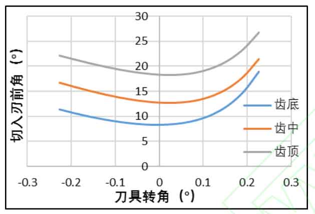
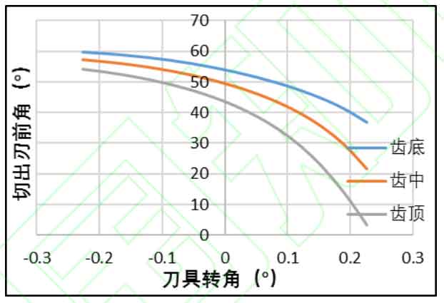
The above figure shows the variation law of the cutting rake angle of the helical gear turning tool with the tool angle. Three points on the bottom, middle and top of the helical gear turning tool edge are selected to output the variation of the cutting rake angle of the tool teeth from cutting in to cutting out the workpiece. It can be seen from the figure that as the cutter teeth cut in to cut out, the front angle of the cutting edge decreases first and then increases, and the front angle of the cutting edge decreases all the time. The front angle of the cutting edge tooth top is the largest and the front angle of the cutting edge tooth top is the smallest. Generally speaking, the front angle is always positive to meet the processing requirements.