
In the field of mechanical transmission, bevel gears play a critical role in transferring motion and power between intersecting shafts. Among various types, cycloid bevel gears have gained significant attention due to their high efficiency in continuous indexing and superior meshing performance, making them a preferred choice for automotive axle applications. However, the high cost of trial cutting and the complexity of machine tool development necessitate advanced simulation techniques to optimize the manufacturing process. This study focuses on the cutting simulation of cycloid bevel gears using a four-axis linkage method, leveraging VERICUT software to model the machining process, analyze tool and workpiece interactions, and validate the results through experimental verification. By developing accurate machine and cutter models, we aim to reduce costs and guide the development of economical CNC milling machines for bevel gear production.
The four-axis linkage milling machine for cycloid bevel gears consists of three linear axes (X, Y, Z) and two rotational axes (C, A). The X and Y axes control the horizontal and vertical movements of the cutter head, simulating the cradle motion during generation, while the Z axis manages the depth of cut. The C axis drives the cutter head rotation via a servo motor and gear reduction, and the A axis controls the workpiece rotation. During the generation process, the workpiece axis A must synchronize with the cutter head axis C for continuous indexing and coordinate with the linear axes X and Y to achieve the generation motion. This four-axis linkage ensures precise tooth formation for cycloid bevel gears. The machine model was developed in UG software and then simplified in VERICUT to create a motion-equivalent model, focusing on the essential kinematic relationships without replicating the full physical structure. This approach allows for efficient simulation of the cutting process while maintaining accuracy.
In VERICUT, the machining simulation model comprises the machine tool, gear blank, and cutter head models, along with NC program code. The machine model was constructed using VERICUT’s component tree functionality to replicate the four-axis linkage, ensuring that the motions of the linear and rotational axes match the actual milling machine. The gear blank model was created in UG based on geometric parameters and imported into VERICUT. For the cutter head, we analyzed the structure of the Gleason TRIAC cutter, which is commonly used for cycloid bevel gears. This cutter features grouped teeth, each consisting of an inside and outside blade, with cutting edges offset from the cutter center and measured in the blade reference plane. The mathematical model of the cutter head was established to define the blade geometry accurately. For an inside blade, the cutting edge vector in the blade coordinate system \( S_{e1} \) is given by:
$$ \mathbf{r}_{e1} = \begin{bmatrix} u \sin \alpha & 0 & u \cos \alpha \end{bmatrix}^T $$
where \( u \) is the blade parameter (positive upwards) and \( \alpha \) is the blade pressure angle. Through coordinate transformation, the cutting edge vector in the cutter head coordinate system \( S_e \) is:
$$ \mathbf{r}_e = \mathbf{M}_{e1e} \mathbf{r}_{e1} $$
Here, \( \mathbf{M}_{e1e} \) is the transformation matrix from \( S_{e1} \) to \( S_e \). A similar approach applies to outside blades, with adjustments for their specific parameters. Using parametric design in UG, we developed a 3D cutter head model that mirrors the actual structure, incorporating key parameters such as cutter radius, number of blade groups, and pressure angles. This model ensures realistic simulation of the cutting process for cycloid bevel gears.
The motion analysis and NC programming for the four-axis generation method involve coordinating the cutter head, cradle, and workpiece. During generation, the workpiece must rotate in sync with the cutter head for indexing and with the linear axes for generation. The relationship between the angular velocities of the workpiece (\( \omega_A \)), cradle (\( \omega_g \)), and cutter head (\( \omega_C \)) is expressed as:
$$ \omega_A = \omega_g + \left( \frac{z_0}{z_p} + \frac{z_0}{z} \right) \omega_C $$
where \( z_0 \) is the number of blade groups, \( z_p \) is the generating gear tooth number, and \( z \) is the workpiece tooth number. To implement this, we used electronic gearing for continuous indexing and linear interpolation for generation motions. The NC program code controls the axes movements, including rapid positioning, roughing cuts, and generation passes. For example, the generation phase involves calculating incremental movements for the X, Y, and A axes based on cradle rotation steps, ensuring precise tooth surface generation for cycloid bevel gears.
The theoretical tooth surface of cycloid bevel gears is derived from the generation method mathematical model. In this process, the cutter head and generating gear undergo relative rolling motions to form the generating gear tooth surface, which then conjugates with the workpiece through cradle rotation. For a left-hand gear, the basic mathematical model involves multiple coordinate systems representing the cutter head, generating gear, and workpiece. The tooth surface equation in the workpiece coordinate system \( S_w \) is given by:
$$ \mathbf{r}_w(u, \phi_t, \phi_g) = \mathbf{M}_{wn} \mathbf{M}_{nm} \mathbf{M}_{mp}(\phi_g) \mathbf{M}_{pe0} \mathbf{M}_{e0e}(\phi_t) \mathbf{r}_e $$
where \( \mathbf{r}_e \) is the cutter edge vector, \( \phi_t \) is the cutter rotation angle, \( \phi_g \) is the cradle angle, and \( \mathbf{M} \) matrices represent coordinate transformations between systems. The meshing equation must also be satisfied:
$$ f(u, \phi_t, \phi_g) = \left( \frac{\partial \mathbf{r}_w}{\partial u} \times \frac{\partial \mathbf{r}_w}{\partial \phi_t} \right) \cdot \frac{\partial \mathbf{r}_w}{\partial \phi_g} = 0 $$
To solve for the numerical tooth surface, we discretize the surface into grids along the tooth length and height directions. For a grid point \( P_{ij} \) with coordinates \( (X_{Lij}, R_{Lij}) \) in the axis section, the corresponding point \( M \) on the tooth surface has spatial coordinates \( (x_M, y_M, z_M) \). The rotation projection relationship yields:
$$ \begin{cases} R_{Lij} = \sqrt{y_M^2 + z_M^2} \\ X_{Lij} = x_M \end{cases} $$
Combining this with the meshing equation, we solve for the parameters \( u \), \( \phi_t \), and \( \phi_g \) using numerical methods like Newton-Raphson, obtaining the 3D coordinates of the tooth surface for cycloid bevel gears.
For the cutting simulation example, we considered a gear pair with a left-hand large gear. The geometric parameters of the gear pair are summarized in Table 1, and the cutting parameters for the large gear are provided in Table 2. Using the VERICUT model, we simulated the cutting process, which included roughing and generation phases. The simulation showed that the machined tooth surface closely matched the theoretical surface, with deviations under 5 μm, confirming the accuracy of the model. Additionally, we verified non-cutting edge parameters to prevent interference; for instance, increasing the non-cutting pressure angles beyond design limits caused overcutting, highlighting the importance of parameter optimization for cycloid bevel gears.
| Parameter | Large Gear | Pinion |
|---|---|---|
| Number of Teeth | 28 | 17 |
| Module (mm) | 10.357 | |
| Pressure Angle (°) | 22.5 | |
| Midpoint Spiral Angle (°) | 35 | |
| Face Width (mm) | 50 | |
| Large End Pitch Diameter (mm) | 290 | 176.07 |
| Whole Depth (mm) | 16.28 | 16.28 |
| Addendum (mm) | 7.24 | 7.24 |
| Pitch Cone Angle (°) | 58.73 | 31.27 |
| Parameter | Value |
|---|---|
| Cutter Radius (mm) | 125 |
| Number of Blade Groups | 13 |
| Blade Pressure Angle (°) | 22.5 |
| Workpiece Installation Angle (°) | 58.74 |
| Radial Tool Position (mm) | 168.5911 |
| Angular Tool Position (°) | 46 |
| Horizontal Workpiece Position (mm) | 0 |
| Vertical Workpiece Position (mm) | 0 |
| Bed Position (mm) | 0 |
| Ratio of Roll | 1.169881 |
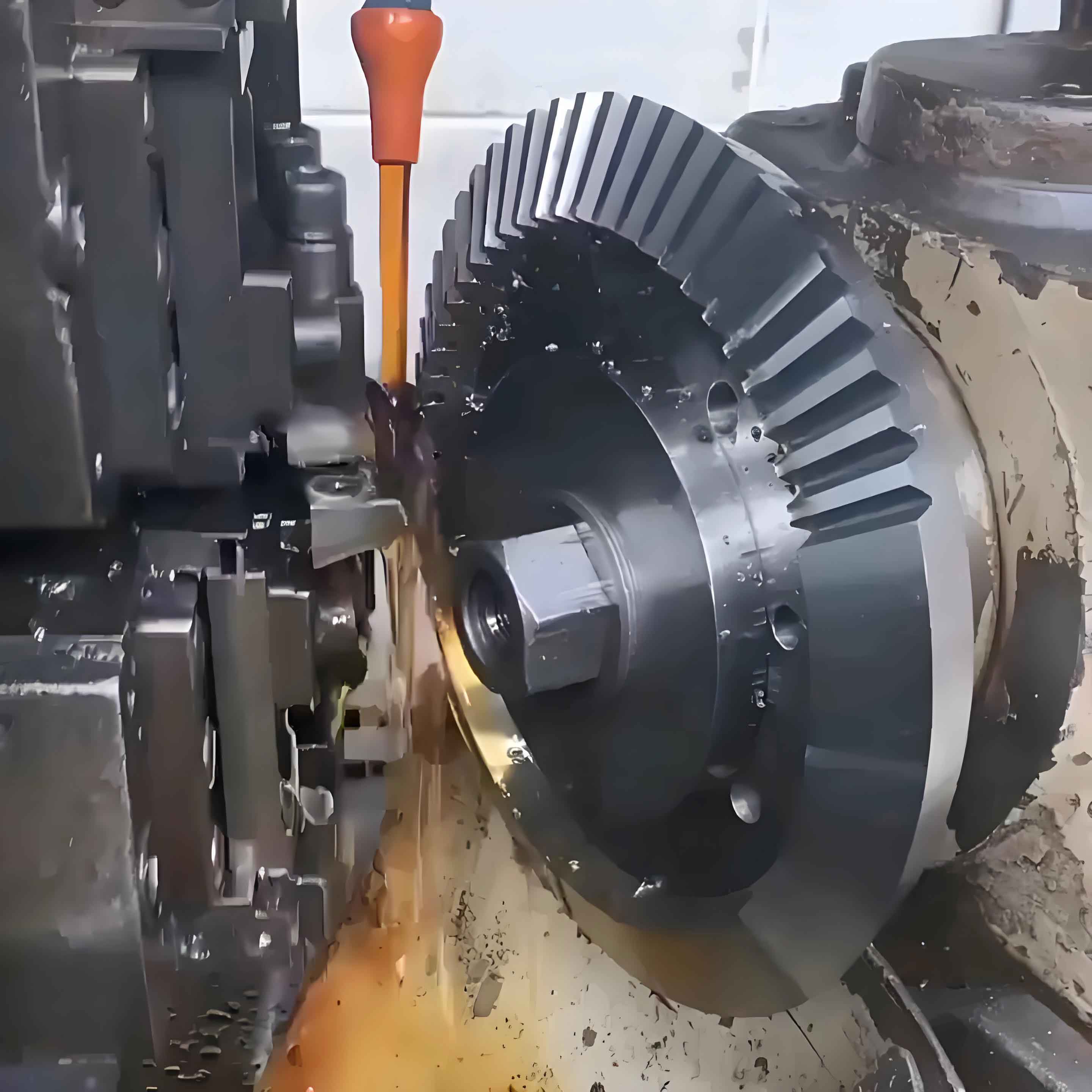
The cutting experiment was conducted on a developed machine tool using the validated NC program. The actual cutting process proceeded smoothly, with proper indexing and no tooth surface interference. The machined gear was measured for tooth surface errors, and the results showed maximum errors below 6 μm, meeting precision requirements. This experimental verification further confirms the correctness of the VERICUT simulation model and demonstrates its utility in guiding machine development and actual cutting processes for cycloid bevel gears.
In conclusion, this research successfully developed a VERICUT-based cutting simulation method for four-axis generation of cycloid bevel gears. By constructing accurate machine and cutter models and analyzing the kinematic relationships, we simulated the cutting process effectively. The comparison between simulated and theoretical tooth surfaces, along with experimental results, validated the method’s accuracy and feasibility. This approach not only reduces trial costs but also supports the development of cost-effective CNC milling machines for bevel gear manufacturing, contributing to advancements in gear technology and industrial applications.