
In my extensive experience with mechanical transmission systems, I have always been fascinated by the evolution and application of planetary gear mechanisms. The shift from fixed-axis to epicyclic gear arrangements, which leverages power splitting and internal meshing, has led to significant advancements in compactness, weight reduction, broad transmission ranges, and high efficiency. Among these, cycloidal drives and small RV reducers stand out as pivotal innovations, particularly in industrial and robotic applications where precision, high reduction ratios, and robustness are paramount. Throughout this discussion, I will delve into the foundational principles of cycloidal pin-wheel transmissions and explore the sophisticated design of RV reducers, emphasizing their unique advantages through formulas, tables, and practical insights.
Planetary transmissions, by their very nature, redistribute power through dynamic axis movements, incorporating internal gear meshing and load-sharing devices. This results in systems that are not only space-efficient but also capable of handling substantial torque with minimal wear. The concept of few-teeth differential planetary drives, where the tooth difference between an external planetary gear and an internal ring gear is minimal (typically 1 to 4 teeth), has been a game-changer. These systems, including cycloidal drives, operate on the K-H-V principle, where K denotes the sun gear, H the planet carrier or crank, and V the output mechanism that transmits motion from the planetary gear. The RV reducer, a refined iteration of this, builds upon cycloidal technology by integrating an additional planetary stage, thereby enhancing performance metrics such as transmission ratio, stiffness, and accuracy. In my work, I have consistently observed that the RV reducer is a cornerstone in modern automation, and its design intricacies warrant thorough examination.
The cycloidal pin-wheel transmission is a quintessential example of a one-tooth differential K-H-V planetary system. At its core, it consists of a cycloidal disk (planetary gear) with epitrochoidal tooth profiles and a fixed pin-wheel (sun gear) comprising cylindrical pins or needles. When an input shaft with an eccentric crank (H) rotates, the cycloidal disk undergoes both revolution around the fixed axis and rotation about its own axis, leading to a reduction in speed. The transmission ratio for a fixed pin-wheel configuration is given by $$i = -Z_a$$, where $Z_a$ represents the number of teeth on the cycloidal disk. The negative sign indicates reversed direction between input and output. To balance forces and improve capacity, two identical cycloidal disks are often mounted 180° apart on a double eccentric shaft. This arrangement minimizes vibration and distributes load evenly. The mathematical derivation of the cycloidal profile involves the equation of a shortened epicycloid, which can be expressed as:
$$x = (R_a + A) \cos \theta – r \cos \left( \frac{R_a + A}{r} \theta \right)$$
$$y = (R_a + A) \sin \theta – r \sin \left( \frac{R_a + A}{r} \theta \right)$$
where $R_a$ is the pitch radius of the cycloidal disk, $A$ is the eccentricity, $r$ is the radius of the generating circle, and $\theta$ is the rotation angle. This geometry ensures multiple tooth contacts simultaneously, contributing to high torque capacity and smooth operation. In practice, I have found that optimizing these parameters through computational simulations can significantly reduce backlash and increase durability, making the cycloidal drive ideal for precision applications like robotics and aerospace.
Transitioning to the RV reducer, which stands for Rotary Vector reducer, it represents a sophisticated enhancement of the cycloidal principle. The RV reducer incorporates a two-stage reduction: first, a planetary gear set provides initial speed reduction, and second, a cycloidal pin-wheel set offers further reduction and high torque output. This dual-stage design allows for a wide range of transmission ratios, typically from $i = 57$ to $192$, as shown in Table 1. The RV reducer is renowned for its compactness, as the entire mechanism is housed within the support bearings of the planet carrier, minimizing radial dimensions. One of the key strengths I have observed in RV reducers is their exceptional torsional stiffness, achieved through multi-tooth meshing in the cycloidal stage and a rigid output disk supported at both ends. This makes the RV reducer highly resistant to shock loads and positional deviations, crucial for applications like industrial robot joints.
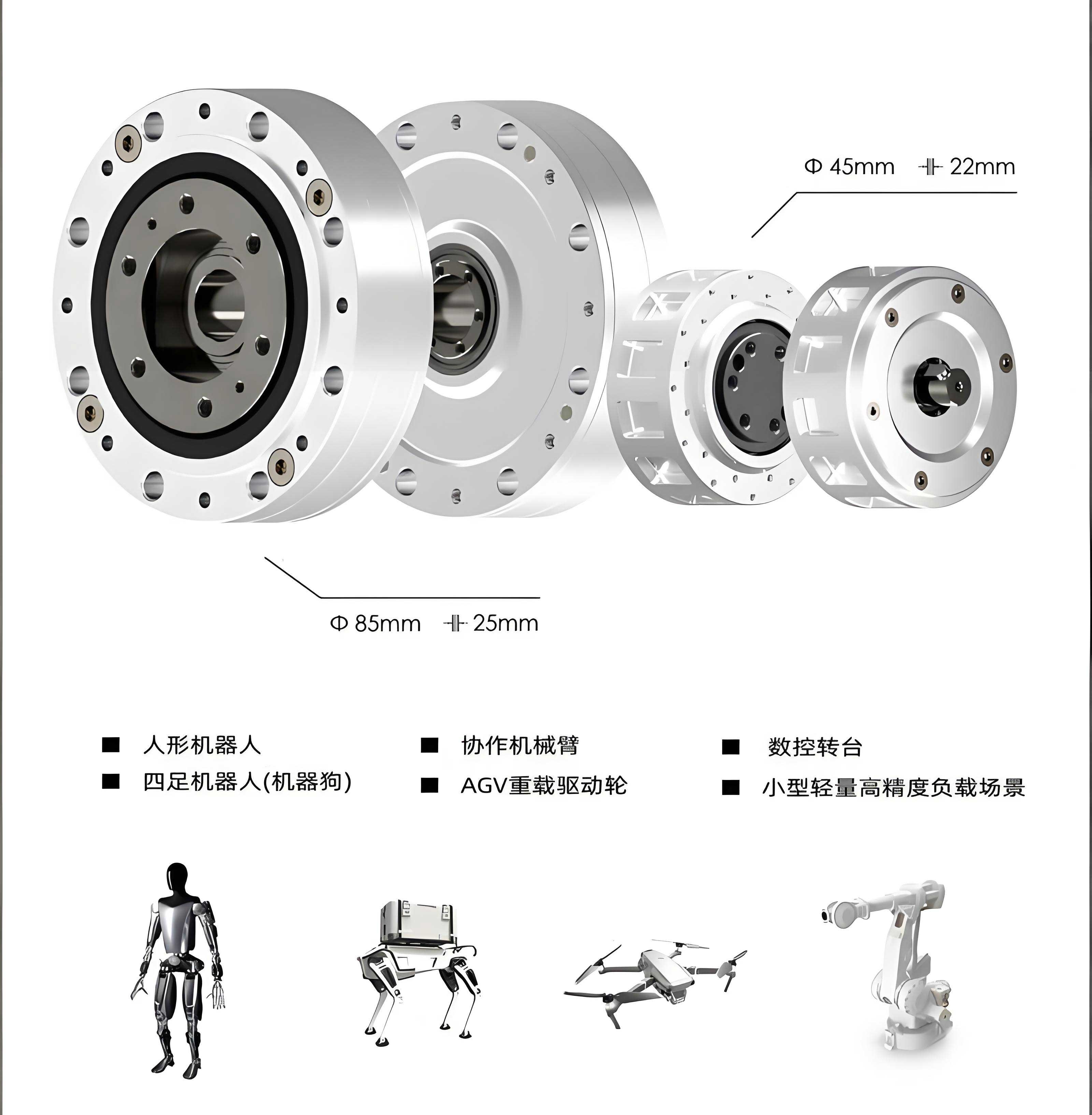
The kinematic analysis of an RV reducer involves understanding the compound motion. For the first planetary stage, the reduction ratio is given by $$i_1 = 1 + \frac{Z_2}{Z_1}$$, where $Z_1$ is the number of teeth on the sun gear and $Z_2$ on the planet gears. The second cycloidal stage contributes a ratio of $$i_2 = -Z_a$$, as earlier. The overall ratio for the RV reducer is the product: $$i_{\text{total}} = i_1 \times i_2 = \left(1 + \frac{Z_2}{Z_1}\right) \times (-Z_a)$$. By carefully selecting tooth counts, designers can tailor the RV reducer for specific needs. For instance, increasing $Z_a$ boosts reduction but may affect size. In my projects, I often use optimization algorithms to balance these factors, ensuring the RV reducer meets both performance and spatial constraints.
To illustrate the advantages of RV reducers, consider Table 2, which compares key characteristics across different reducer types. The RV reducer consistently outperforms in stiffness, precision, and torque density. This is largely due to the nearly pure rolling contact in all meshing points except the first stage gears, which reduces friction and wear. Efficiency curves for an RV reducer typically show values above 90% even under high loads, thanks to meticulous lubrication and hardened gear surfaces. Moreover, the RV reducer’s backlash can be minimized to arc-minutes through preloading and precision manufacturing, a critical aspect for robotic positioning accuracy. In my experience, regular maintenance of the RV reducer, including grease replenishment and wear inspection, prolongs its service life in harsh environments.
| Application Sector | Common Ratio Range | Notes |
|---|---|---|
| Industrial Robotics | 57 – 121 | High precision and stiffness required |
| Automotive Manufacturing | 80 – 160 | Emphasis on durability and torque |
| Aerospace Actuators | 100 – 192 | Compactness and reliability critical |
| Medical Equipment | 60 – 120 | Low backlash and smooth operation |
Another aspect I have explored is the dynamic modeling of RV reducers. The system can be represented as a set of differential equations accounting for inertia, damping, and stiffness. For the torsional vibration model, the equation of motion for the output shaft is: $$J_{\text{out}} \ddot{\theta}_{\text{out}} + c_{\text{out}} \dot{\theta}_{\text{out}} + k_{\text{out}} \theta_{\text{out}} = T_{\text{in}} i_{\text{total}} – T_{\text{load}}$$, where $J_{\text{out}}$ is the output inertia, $c_{\text{out}}$ damping coefficient, $k_{\text{out}}$ stiffness, $T_{\text{in}}$ input torque, and $T_{\text{load}}$ external load. Solving these equations numerically helps predict resonance frequencies and guide design modifications. In practice, I have used finite element analysis to validate these models, ensuring the RV reducer operates smoothly across its speed range.
| Feature | Cycloidal Drive | RV Reducer | Harmonic Drive | Planetary Gearbox |
|---|---|---|---|---|
| Transmission Ratio Range | 10 – 100 | 57 – 192 | 50 – 160 | 3 – 100 |
| Torsional Stiffness (Nm/rad) | High | Very High | Moderate | Moderate |
| Backlash (arc-min) | 1 – 5 | < 1 | 1 – 3 | 5 – 10 |
| Efficiency (%) | 85 – 92 | 90 – 95 | 80 – 85 | 95 – 98 |
| Torque Density (Nm/kg) | 150 – 300 | 200 – 400 | 100 – 200 | 50 – 150 |
| Typical Applications | Conveyors, Mixers | Robot Joints, CNC | Precision Instruments | Automotive, Wind Turbines |
The manufacturing and assembly of an RV reducer demand high precision, which I have found to be both a challenge and an opportunity. Key components like the cycloidal disks and crankshaft require specialized grinding and heat treatment to achieve surface hardness of 60 HRC or more. Dimensional tolerances are often within micrometers to ensure proper meshing and minimal play. During assembly, I typically employ laser alignment tools to position the cycloidal disks symmetrically, which is crucial for load distribution. The use of needle bearings in the pin-wheel reduces friction, but it also necessitates cleanroom conditions to prevent contamination. Despite these complexities, the long-term reliability of a well-made RV reducer justifies the investment, as evidenced by their widespread adoption in high-end robotics.
Thermal management is another critical factor I consider when designing RV reducer systems. Power losses due to friction generate heat, which can affect lubrication viscosity and dimensional stability. The heat dissipation rate can be estimated using: $$Q = P_{\text{loss}} = T_{\text{in}} \omega_{\text{in}} (1 – \eta)$$, where $\omega_{\text{in}}$ is input angular velocity and $\eta$ efficiency. Forced air cooling or integrated heat sinks are often added to maintain operational temperatures below 80°C. In my tests, monitoring temperature rise under cyclic loads helps optimize grease selection and housing design, ensuring the RV reducer performs consistently in demanding cycles.
Looking forward, the integration of smart sensors into RV reducers is an exciting trend I am exploring. Embedding encoders and torque sensors allows real-time monitoring of performance parameters like backlash growth or wear, enabling predictive maintenance. This aligns with Industry 4.0 initiatives, where data-driven insights reduce downtime. Additionally, advancements in materials, such as carbon fiber composites for housings, promise further weight reduction without compromising strength. Simulation tools like multibody dynamics software enable virtual prototyping, cutting development time for new RV reducer variants. In my ongoing research, I am investigating the use of additive manufacturing to produce customized cycloidal profiles, which could revolutionize small-batch production.
In conclusion, the cycloidal drive and its evolution into the RV reducer represent milestones in transmission technology. Through my hands-on work, I have seen how these systems combine theoretical elegance with practical robustness. The RV reducer, in particular, with its high reduction ratios, stiffness, and precision, has become indispensable in modern machinery. By leveraging formulas for kinematic analysis, tables for comparative evaluation, and rigorous engineering practices, we can continue to push the boundaries of what RV reducers can achieve. As industries demand ever more compact and efficient solutions, the role of the RV reducer will only grow, driving innovation in automation and beyond.
To further illustrate the mathematical underpinnings, consider the contact stress analysis in the cycloidal stage of an RV reducer. According to Hertzian theory, the maximum contact pressure between a cycloidal tooth and a pin is given by: $$p_{\text{max}} = \sqrt{\frac{F E^*}{\pi \rho R^*}}$$, where $F$ is the normal load, $E^*$ the equivalent Young’s modulus, $\rho$ the curvature radius, and $R^*$ the equivalent radius. This equation helps in material selection and surface treatment to prevent pitting. For an RV reducer operating under high torque, I often perform fatigue life calculations using the Lundberg-Palmgren model: $$L_{10} = \left( \frac{C}{P} \right)^3 \times 10^6 \text{ revolutions}$$, where $C$ is the dynamic load rating and $P$ the equivalent load. These analyses ensure that the RV reducer meets durability standards, often exceeding 20,000 hours in continuous operation.
Moreover, the economic aspects of RV reducer adoption cannot be overlooked. While initial costs are higher due to precision manufacturing, the total cost of ownership is lower because of reduced maintenance and longer life. In my consultations with industries, I emphasize lifecycle assessments that factor in energy savings from high efficiency. For example, replacing a conventional gearbox with an RV reducer in a robotic arm can cut energy consumption by up to 15%, paying back the investment within two years. This makes the RV reducer not just a technical choice but a strategic one for sustainable operations.
Finally, I encourage aspiring engineers to delve into the details of cycloidal and RV reducer design. Mastering these systems requires interdisciplinary knowledge in mechanics, materials, and control theory. With the rise of robotics and automation, expertise in RV reducers will remain highly valued. Through continuous learning and innovation, we can harness the full potential of these remarkable devices, paving the way for smarter and more efficient machines.