1. Introduction
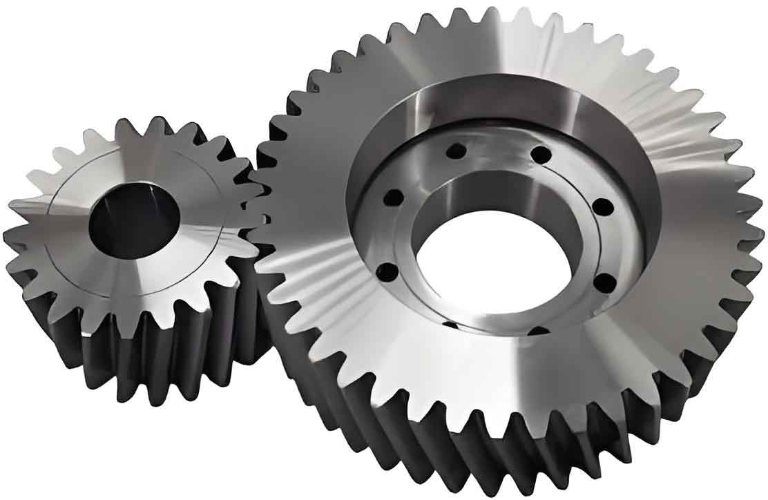
Cylindrical gears are among the most widely used mechanical components in power transmission systems. Traditional cylindrical gears, such as spur gears, helical gears, and herringbone gears, each have limitations in terms of load capacity, noise generation, axial forces, or manufacturing efficiency. For instance:
- Spur gears are simple to manufacture but suffer from low contact ratios and vibration.
- Helical gears offer smoother operation but generate axial forces that complicate bearing designs.
- Herringbone gears eliminate axial forces but require complex machining processes and undercut regions that reduce tooth utilization.
Recent advancements in curvilinear-tooth cylindrical gears (e.g., circular-arc tooth traces) have addressed some limitations. However, these gears still face challenges in efficient manufacturing, as they rely on time-consuming, tooth-by-tooth indexing methods.
This study introduces a novel cycloidal cylindrical gear that combines the benefits of high load capacity, smooth transmission, and continuous-index milling. Unlike traditional gears, its tooth profile follows a cycloidal curve along the axial direction, enabling rapid machining with minimal tool adjustments.
2. Mathematical Modeling of Cycloidal Cylindrical Gears
2.1 Generation of Cycloidal Tooth Profile
The tooth profile is derived from the rolling motion of a base circle CC (radius RbRb) along a generating rack. A point MM on the circle traces a cycloid, which forms the gear’s tooth shape. The parametric equations for the cycloid are:{X0=Rbθ−RtsinθY0=−Rtcosθ{X0=Rbθ−RtsinθY0=−Rtcosθ
where RtRt is the distance from the circle center to point MM, and θθ is the rolling angle.
2.2 Meshing Theory and Contact Conditions
The meshing equation ensures continuous contact between the gear and rack. For a point MM on the rack, the relative velocity v(12)v(12) must satisfy:v(12)⋅n=0v(12)⋅n=0
where nn is the common normal vector at the contact point. This condition guarantees no separation or interference during rotation.
2.3 Discrete Point Generation and 3D Modeling
Using self-developed software, discrete points on the tooth surface are calculated and imported into SolidWorks for 3D model construction. Key parameters are summarized in Table 1.
Table 1: Key Parameters for 3D Modeling
| Parameter | Range/Value |
|---|---|
| uu (mm) | -7 to 7 |
| θθ (°) | 52 to 92 |
| RbRb (mm) | 30 |
| RtRt (mm) | 105 |
| Pressure Angle | 20° |
3. Machining Principles and Tool Design
3.1 Disc Milling Cutter Geometry
The cycloidal cylindrical gear is machined using a disc milling cutter with replaceable blades. Key features include:
- Modular Blades: Adjustable radially and circumferentially to accommodate different gear modules.
- Standardization: A single disc cutter can machine gears of varying modules by swapping blades.
Table 2: Disc Cutter Design Parameters
| Parameter | Value/Range |
|---|---|
| Disc Diameter (D1D1) | 150 mm |
| Blade Number (Z1Z1) | 12 |
| Blade Angle (αα) | 20° |
| Radial Adjustment (drdr) | ±2 mm |
3.2 Continuous-Index Milling Process
The workpiece and cutter rotate synchronously to simulate the rack-gear meshing motion. The angular velocity ratio is given by:ω1ω2=Rp2Rbω2ω1=RbRp2
where ω1ω1 and ω2ω2 are the cutter and workpiece speeds, Rp2Rp2 is the gear’s pitch radius, and RbRb is the base circle radius. This method eliminates tool retraction, enabling uninterrupted machining.
4. Advantages of Cycloidal Cylindrical Gears
Table 3: Comparison with Traditional Cylindrical Gears
| Feature | Spur Gear | Helical Gear | Cycloidal Gear |
|---|---|---|---|
| Axial Force | None | High | None |
| Contact Ratio | Low (1.0–1.5) | Moderate (1.5–2.0) | High (≥2.3) |
| Manufacturing Efficiency | Moderate | Low | High |
| Tool Standardization | Low | Low | High |
Key advantages include:
- High Load Capacity: The cycloidal profile distributes stress evenly, reducing wear.
- No Axial Force: Simplifies bearing and housing designs.
- Efficient Machining: Continuous-index milling reduces production time by 40–60%.
5. Limitations and Future Work
While cycloidal cylindrical gears excel in many areas, limitations remain:
- Size Constraints: Large-diameter gears (≥1 m≥1m) require alternative machining methods.
- Parameter Sensitivity: Optimal cycloid parameters (Rb,RtRb,Rt) depend on gear size and application.
Future research will focus on:
- Optimization Algorithms: For automated parameter selection.
- Hybrid Tooling: Combining disc cutters with CNC grinding for larger gears.
6. Conclusion
This study presents a groundbreaking approach to designing and manufacturing cycloidal cylindrical gears, combining high performance with rapid production. By leveraging cycloidal tooth profiles and continuous-index milling, these gears address longstanding challenges in power transmission systems. The methodology and tools developed here provide a foundation for advancing cylindrical gear technology across industries.
Appendices
Appendix A: Nomenclature
| Symbol | Definition |
|---|---|
| RbRb | Base circle radius |
| RtRt | Tracing point radius |
| ωω | Angular velocity |
Appendix B: Sample Gear Parameters
| Parameter | Gear 1 | Gear 2 | Rack |
|---|---|---|---|
| Teeth Number | 30 | 20 | 12 |
| Module (mm) | 5 | 5 | 5 |
| Pitch Diameter (mm) | 150 | 100 | 60 |
