
In my extensive career focusing on process optimization within chemical and metallurgical industries, I have consistently sought methodologies and mechanical systems that enhance precision, efficiency, and environmental sustainability. A recurring theme in my work involves the analysis of critical contaminants like cyanide and the recovery of precious metals, processes where reliable mechanical agitation is paramount. It is in this context that the cycloidal drive has emerged as a transformative technology. This article details my first-hand perspective on integrating analytical techniques with advanced mechanical design, with a particular emphasis on the unparalleled advantages offered by the cycloidal drive in industrial mixing applications. The principles discussed are broadly applicable, bridging the gap between precise chemical measurement and robust physical processing.
The accurate determination of trace cyanide in industrial wastewater and common water sources is a fundamental requirement for environmental compliance and process control. While sophisticated instruments like spectrophotometers enable precise quantification using methods such as the isonicotinic acid-pyrazolone or pyridine-barbituric acid techniques, there exists a practical need for reliable, semi-quantitative field or plant-floor assays. One method I have employed involves a colorimetric reaction using pyridine with a derivatized benzidine compound. The core principle relies on the formation of a colored complex whose intensity, proportional to cyanide concentration, can be visually compared to a pre-calibrated scale or measured with simple photometric devices. The reaction kinetics and stoichiometry can be described to illustrate the process.
Consider the generic reaction where cyanide ion (CN⁻) reacts with a reagent system (Py-BH, representing the pyridine-based compound) to form a colored product (P_colored). The rate of formation under controlled conditions can be expressed as:
$$ \frac{d[P_{\text{colored}}]}{dt} = k [\text{CN}^-]^m [\text{Py-BH}]^n $$
where \( k \) is the rate constant, and \( m \) and \( n \) are the reaction orders. For semi-quantitative analysis, under conditions of reagent excess (\( n \approx 0 \)), the color development becomes pseudo-first-order relative to cyanide concentration, simplifying the calibration. The limit of detection (LOD) for such a method can be approximated from the calibration curve’s standard deviation (\( \sigma \)) and slope (\( S \)):
$$ \text{LOD} = \frac{3.3 \sigma}{S} $$
The practicality of this assay lies in its operational simplicity, sharp color transition, and sufficient accuracy for rapid screening, making it a viable option when immediate decisions are required prior to confirmatory analysis via standard methods. The following table contrasts its characteristics with other established techniques.
| Method | Principle | Approximate LOD (mg/L) | Equipment Needs | Best Use Case |
|---|---|---|---|---|
| Pyridine-Benzidine Semi-Quantitative | Colorimetric complexation | 0.01 – 0.05 | Minimal (test tubes, comparator) | Field screening, plant control lab |
| Isonicotinic-Pyrazolone Spectrophotometry | Spectrophotometric absorption | 0.001 – 0.005 | Spectrophotometer | Regulatory compliance, precise quantification |
| Ion Chromatography | Ion separation & conductivity detection | 0.001 – 0.01 | Ion Chromatograph | Simultaneous anion analysis |
| Ion Selective Electrode | Potentiometric measurement | 0.01 – 0.1 | ISE meter, reference electrode | Continuous monitoring, on-line analysis |
Transitioning from analytical chemistry to process engineering, efficient mixing is a critical unit operation, especially in hydrometallurgical processes like gold extraction via cyanidation or adsorption. Here, the choice of drive mechanism for the agitator directly impacts energy consumption, maintenance cycles, and process reliability. My investigations have repeatedly shown that conventional gear reducers or V-belt drives fall short in harsh, continuous-duty environments common in mineral processing. This is where the cycloidal drive, or cycloidal speed reducer, becomes indispensable. The elegance of the cycloidal drive lies in its unique kinematic principle, which offers high torque transmission, exceptional shock load tolerance, and remarkably high efficiency in a compact form factor.
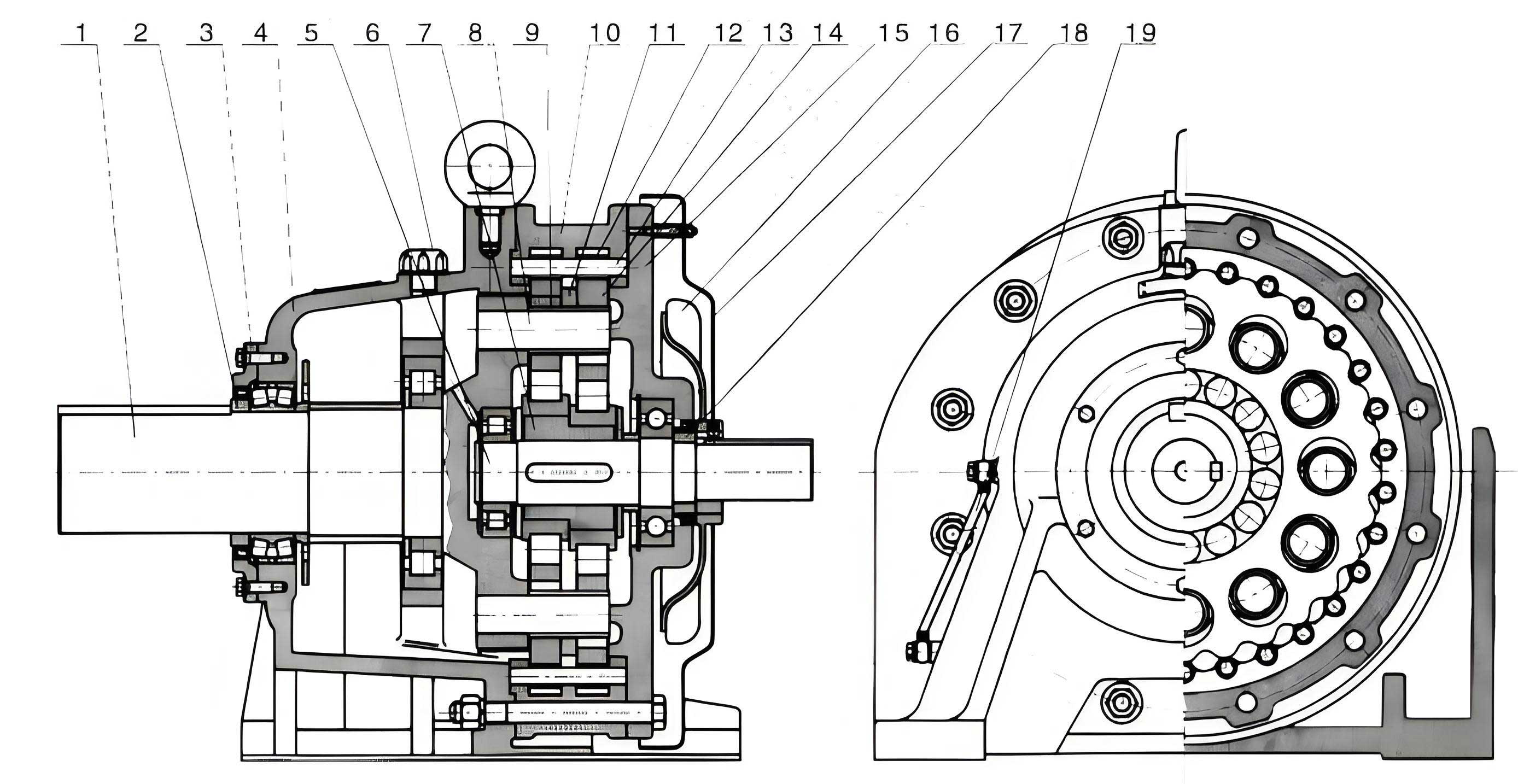
The fundamental operation of a cycloidal drive involves an eccentric input cam that causes a cycloidal disc to undergo a compound motion: rotation and eccentric wobbling. This motion is then translated into slow, high-torque output via a series of stationary pins and rollers. The kinematic relationship defining the reduction ratio (\( i \)) of a single-stage cycloidal drive is given by:
$$ i = \frac{N_p}{N_p – N_d} $$
where \( N_p \) is the number of pins on the stationary ring, and \( N_d \) is the number of lobes on the rotating cycloidal disc. Typically, \( N_d = N_p – 1 \), leading to a high reduction ratio \( i = N_p \). For instance, if \( N_p = 40 \), then \( i = 40 \). The mechanical efficiency (\( \eta \)) of a well-lubricated cycloidal drive can be modeled considering friction losses at the roller contacts and bearings:
$$ \eta \approx 1 – \sum \left( \frac{\mu_k F_n}{T_{\text{out}} \omega_{\text{out}}} \right) \approx 90\% – 95\% $$
where \( \mu_k \) is the coefficient of kinetic friction, \( F_n \) is the normal force at contact points, \( T_{\text{out}} \) is the output torque, and \( \omega_{\text{out}} \) is the output angular velocity. This high efficiency is a cornerstone of its energy-saving potential. The compactness and durability of the cycloidal drive are visually apparent in its design, as shown below.
In the specific application of a leaching or adsorption tank for gold ore, the agitator must handle abrasive slurries, provide consistent gas dispersion if aerated, and operate continuously with minimal downtime. A stirrer equipped with a cycloidal drive directly addresses these demands. The high torque density allows for the use of a smaller motor while still driving large impellers through viscous media. The inherent shock absorption protects the motor and gearbox from sudden load changes caused by settling solids. To quantify the benefits, let’s compare a standard helical gear drive with a cycloidal drive for a hypothetical 100 kW mixing application.
| Performance Parameter | Helical Gear Reducer | Cycloidal Drive Reducer |
|---|---|---|
| Reduction Ratio Range (Single Stage) | 3:1 to 100:1 | 10:1 to 119:1 (and higher) |
| Theoretical Efficiency at Full Load | 94-97% | 90-95% |
| Overhung Load Capacity | Moderate | Very High |
| Shock Load Tolerance | Low to Moderate | Excellent |
| Footprint & Weight for same torque | Larger & Heavier | Compact & Lighter (up to 50% savings) |
| Estimated Maintenance Interval | 8,000 – 12,000 hours | 15,000 – 20,000 hours |
| Noise Level (dB at 1m) | 75 – 85 | 65 – 75 |
The integration of a cycloidal drive into a stirred tank system extends beyond the drive itself. For gold processing, the agitation system often includes aeration. A well-designed setup pairs the cycloidal drive with a hollow agitator shaft and a sealed air supply system. The rotational stability provided by the cycloidal drive ensures uniform gas dispersion, which is critical for maintaining optimal dissolved oxygen levels in cyanide leaching or for promoting effective carbon adsorption. The mechanical integrity also allows for the use of cost-effective abrasion-resistant linings, such as cast basalt tiles, within the tank without fear of excessive vibration causing liner failure.
Let’s consider the process of gold recovery from secondary sources, such as electroplating scraps, which involves chemical stripping and electrolytic deposition. A key step is the agitation of the stripping solution to ensure uniform contact and temperature. A tank agitated by a cycloidal drive-powered mixer enhances heat and mass transfer, speeding up the dissolution kinetics. The governing equation for mass transfer at the solid-liquid interface can be expressed as:
$$ J = k_L (C_s – C_b) $$
where \( J \) is the flux of gold into solution, \( k_L \) is the liquid-phase mass transfer coefficient, \( C_s \) is the concentration at the solid surface (related to solubility), and \( C_b \) is the bulk concentration. The coefficient \( k_L \) is strongly influenced by the agitator’s power input per unit volume (\( P/V \)), which is delivered efficiently and consistently by the robust cycloidal drive. The power number (\( N_p \)) for a given impeller type relates power (\( P \)) to operational parameters:
$$ P = N_p \rho N^3 D^5 $$
Here, \( \rho \) is fluid density, \( N \) is impeller rotational speed (directly set by the output of the cycloidal drive), and \( D \) is impeller diameter. The stability of \( N \) provided by the cycloidal drive, despite varying slurry densities, ensures a predictable \( k_L \) and, consequently, a more controlled and efficient stripping process.
The advantages of the cycloidal drive are further magnified when considering system dynamics and control. The high rigidity and low backlash of the cycloidal drive improve the responsiveness of the mixing system to control signals. For instance, if process conditions require a change in agitation speed to optimize cyanide concentration or pH control in a leaching circuit, the cycloidal drive responds with minimal lag. This can be modeled by considering the system’s moment of inertia (\( I \)) and the drive’s torsional stiffness (\( k_t \)). The simplified equation of motion for the output shaft is:
$$ I \frac{d^2\theta}{dt^2} + c \frac{d\theta}{dt} + k_t \theta = T_{\text{drive}} – T_{\text{load}} $$
where \( \theta \) is the angular displacement, \( c \) is a damping coefficient, \( T_{\text{drive}} \) is the torque from the cycloidal drive, and \( T_{\text{load}} \) is the resisting torque from the fluid. The high \( k_t \) inherent in the cycloidal drive design minimizes angular deflection under varying \( T_{\text{load}} \), leading to more stable process conditions.
From a lifecycle cost perspective, the initial investment in a cycloidal drive is often justified by its longevity and reduced operational expenses. The design, with fewer sliding friction surfaces and rolling contact stresses distributed over many pins, leads to exceptionally low wear rates. The mean time between failures (MTBF) for a cycloidal drive in a 24/7 mixing application can be estimated using reliability engineering models. If we assume the failure rate (\( \lambda \)) follows a Weibull distribution, the reliability function \( R(t) \) is:
$$ R(t) = e^{-(t/\eta)^\beta} $$
where \( \eta \) is the scale parameter (characteristic life) and \( \beta \) is the shape parameter. For a well-maintained cycloidal drive, \( \beta > 1 \), indicating a wear-out failure mode, but with a very large \( \eta \) often exceeding 60,000 hours, demonstrating superior durability compared to alternative drives.
In conclusion, my professional journey has underscored the importance of selecting the right tool for each task—be it a simple chemical test for cyanide or a complex mechanical drive for industrial mixing. The cycloidal drive stands out as a masterpiece of mechanical engineering that directly addresses the core needs of modern processing plants: reliability, efficiency, compactness, and low maintenance. Its application in gold processing, from leaching tanks to recovery circuits, enhances overall plant performance and economics. By coupling robust mechanical systems like the cycloidal drive with sound analytical practices, industries can achieve safer, more sustainable, and more profitable operations. The continued evolution and adoption of the cycloidal drive principle across various sectors is a testament to its fundamental advantages, and I anticipate its role will only grow as demands for process intensification and energy efficiency increase.