
As a precision mechanical component widely adopted across numerous industrial sectors, the cycloidal drive represents a pinnacle of compact power transmission technology. Its operational excellence, characterized by high efficiency, substantial load-bearing capacity, and extended service life, is well-documented. However, this very compactness often leads to the misconception that it requires minimal attention, potentially precipitating operational failures that compromise performance and longevity. Through years of professional engagement with power transmission systems, I have observed that the sustained realization of a cycloidal drive’s inherent advantages is inextricably linked to a regimented and informed maintenance protocol. This treatise aims to elucidate the fundamental operating principles, provide a detailed mathematical foundation, and establish a comprehensive framework for the inspection, maintenance, and optimization of cycloidal drives, ensuring they operate at their theoretical peak.
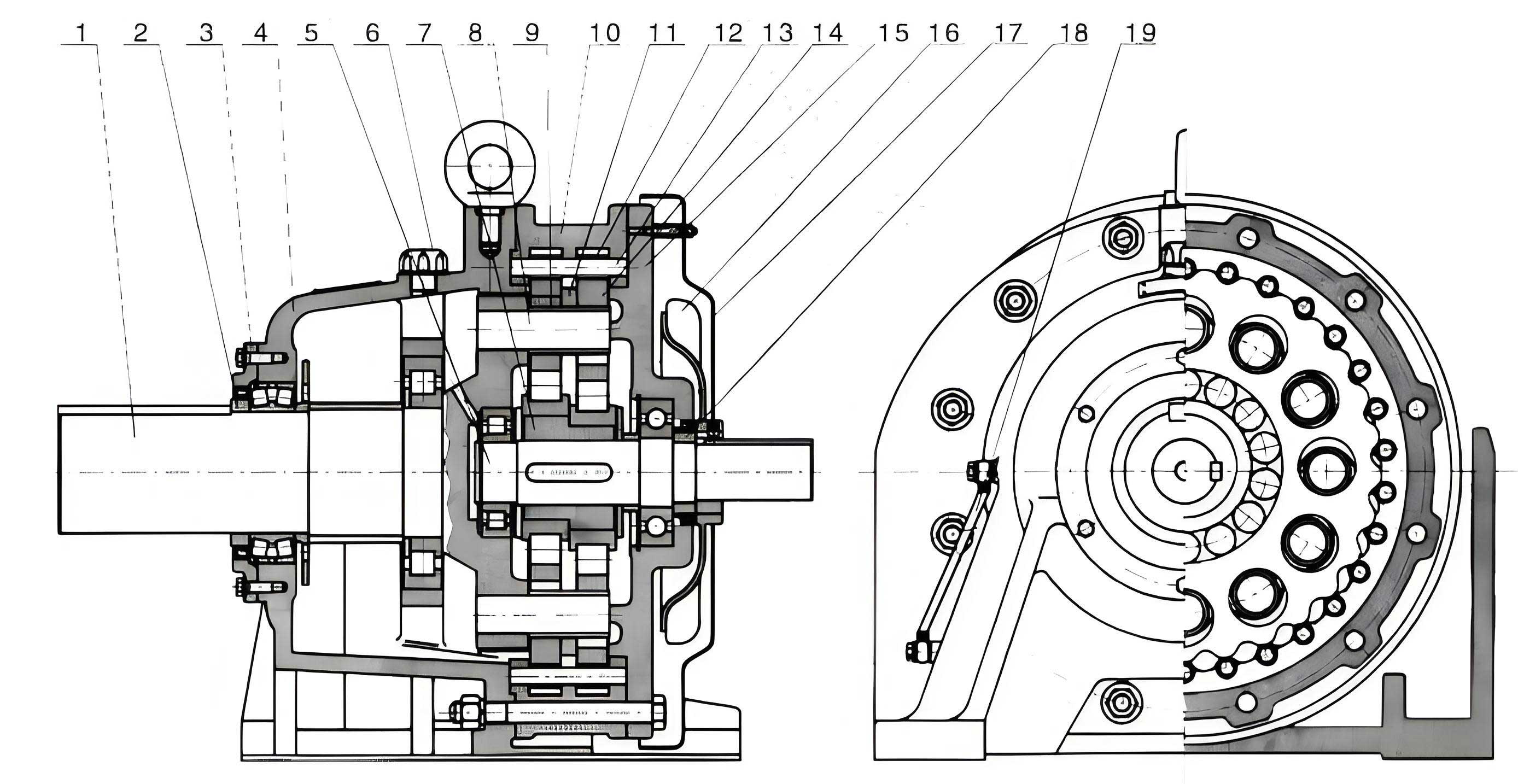
The operational heart of a single-stage cycloidal drive is a sophisticated application of K-H-V type planetary gearing with a small tooth difference. Unlike conventional involute gear systems, this mechanism employs a unique geometry. The system comprises a high-speed input shaft, an eccentric cam or bearing (the H component), one or two cycloidal disks (planets), a static ring gear with cylindrical pins (the internal gear, K component), and an output mechanism, typically a wobble plate or pin-and-crank arrangement (the V component). The defining feature is the cycloidal profile of the disk’s lobes, which meshes with the cylindrical pins of the ring gear. The tooth count difference, or lobe-pin difference, is typically 1, creating a high reduction ratio in a single stage. The fundamental kinematic principle is straightforward: the input eccentric causes the cycloidal disk to undergo a compound epicyclic motion—a revolution around the ring gear’s center (translation) combined with a slow reverse rotation about its own axis. This reverse rotation, significantly reduced in speed, is extracted by the output mechanism. For a cycloidal drive with a single disk, the theoretical reduction ratio is given by:
$$
i = -\frac{Z_p}{Z_p – Z_c}
$$
where \(Z_p\) is the number of pins in the ring gear and \(Z_c\) is the number of lobes on the cycloidal disk. The negative sign indicates direction reversal. Since \(Z_p – Z_c = 1\) for a standard high-ratio design, the formula simplifies to \(i = -Z_p\), meaning the reduction ratio is equal to the number of ring gear pins. This elegant relationship underscores the compactness of the cycloidal drive.
The geometric generation of the cycloidal disk profile is critical for understanding its performance. The ideal profile is an equidistant curve, or envelope, derived from a family of circles (representing the pins) as they roll around a base circle. The parametric equations for the center of a rolling circle (generating pin) are:
$$
\begin{aligned}
x_g &= (R_p + R_r) \cos(\theta) – e \cos\left(\frac{Z_p + 1}{Z_p} \theta\right) \\
y_g &= (R_p + R_r) \sin(\theta) – e \sin\left(\frac{Z_p + 1}{Z_p} \theta\right)
\end{aligned}
$$
where \(R_p\) is the pitch radius of the pin circle, \(R_r\) is the roller (pin sleeve) radius, \(e\) is the eccentricity, and \(\theta\) is the input rotation angle. The actual lobe profile is the inner envelope of circles of radius \(R_r\) centered on this trajectory. Modern cycloidal drives often use modified profiles (like circular-arc or equidistant curves offset from the true epicycloid) to optimize contact stress and facilitate manufacturing.
The static force analysis within a cycloidal drive reveals the sources of its high load capacity. During operation, load is transmitted through multiple lobes simultaneously—a phenomenon known as multi-lobe contact. Assuming \(n\) lobes are in contact, the force transmitted through each contact point can be approximated. The torque \(T_{out}\) on the output is related to the force \(F_i\) on the \(i\)-th contacting lobe by the geometry of the output mechanism. For a standard pin-type output mechanism with pins at radius \(R_{out}\), the relationship is:
$$
T_{out} = R_{out} \sum_{i=1}^{n} F_i \sin(\phi_i)
$$
where \(\phi_i\) is the pressure angle at the \(i\)-th contact. The pressure angle in a well-designed cycloidal drive remains low (often below 30°), which minimizes radial forces and maximizes the tangential component useful for torque transmission. This distribution of force across several lobes drastically reduces contact stress compared to a single-tooth-contact gear mesh, directly contributing to the renowned durability and overload capacity of the cycloidal drive.
| Component | Primary Function | Key Characteristics & Failure Modes |
|---|---|---|
| Cycloidal Disk (Lobes) | Meshes with pins to convert eccentric motion to low-speed rotation. | Hardened steel. Failure: pitting, spalling on lobe flanks due to contact fatigue or abrasive wear. |
| Ring Gear Pins & Rollers | Static internal gear elements providing reaction force. | Case-hardened pins with needle roller sleeves. Failure: roller brinelling, pin bending, roller end wear. |
| Eccentric Bearing (H) | Converts input shaft rotation to eccentric motion of the disk. | Needle or cylindrical roller bearing. Failure: fatigue spalling, cage damage due to high cyclic loads. |
| Output Mechanism Pins/Bearings | Extracts low-speed rotation from the wobbling disk. | Precision pins in bushings or bearings. Failure: wear, fretting, seizure due to high specific pressure. |
| Housing & Seals | Contains components, retains lubricant, excludes contaminants. | Cast iron or aluminum. Seal failure leads to lubricant leakage and ingress of abrasive particles. |
The longevity of any cycloidal drive is a direct function of its operating environment. While designed for continuous duty, thermal management is paramount. The recommended ambient temperature ceiling is typically 40°C. Exceeding this threshold accelerates lubricant degradation and thermal expansion, altering critical clearances. In high-temperature applications, auxiliary cooling via fan kits, heat exchangers, or strategic placement of thermal barriers is not optional but essential. Conversely, in cold starts, lubricant viscosity must be suitable to prevent starvation and excessive torque during run-in. The foundation for the entire system is rigidity and alignment. A flexible or misaligned mount induces parasitic loads, directly counteracting the drive’s inherent force-balancing benefits. Regular checks of base plate flatness, fastener torque, and the alignment of connected shafts (using laser or dial indicators) are fundamental. The consequences of misalignment in a cycloidal drive are severe, leading to accelerated wear on the output pins and bearing, and potentially causing catastrophic failure of the eccentric bearing.
Lubrication is the lifeblood of the cycloidal drive. The system demands a lubricant that can withstand extreme pressure (EP) at the lobe-pin contacts, provide adequate film strength for the eccentric and output bearings, and resist oxidation at operational temperatures. The choice between synthetic and mineral-based oils depends on the operational envelope. Synthetics offer superior thermal stability and lower friction for high-speed or temperature-extreme applications. The lubrication regimen must be meticulously followed, as outlined in the table below, which expands on basic guidelines to include viscosity considerations.
| Operating Condition | Initial Oil Change | Subsequent Change Interval | Recommended Oil Type (ISO VG Example)** |
|---|---|---|---|
| Initial Run-in (All Drives) | After first 150-200 hours | N/A | ISO VG 150-320 (per mfr. spec) |
| Continuous Duty (>8h/day, Standard Temp) | As above | Every 3-4 months | ISO VG 220-320 |
| Intermittent Duty (<8h/day) | As above | Every 6-8 months | ISO VG 150-220 |
| High Ambient Temperature (>40°C) | As above | Reduce interval by 30-50% | Synthetic, ISO VG 220-460 |
| Dusty, Contaminated Environment | As above | Reduce interval by 50% or more | Same viscosity, but monitor condition aggressively. |
| Low-Speed, High-Torque | As above | Standard interval may apply | High EP, ISO VG 320-680 |
** Note: ISO Viscosity Grade (VG) is a critical selection parameter. Always consult the manufacturer’s final specification, as it considers specific bearing and gear geometry.
The integrity of the sealing system is the primary defense against lubricant loss and contaminant ingress. The output shaft seal is a consumable item. Its failure mode is gradual, often starting as minor weeping and progressing to significant leakage. Proactive replacement based on operating hours (e.g., every 8,000-12,000 hours) is more cost-effective than reactive repairs prompted by bearing failure. When replacing seals, the shaft surface must be inspected for wear grooves; if present, a speedy sleeve repair may be necessary to ensure the new seal lips function correctly. For inputs in severely contaminated environments, additional protective measures such as flinger labyrinths or external felt wipers can significantly extend seal and internal component life.
A critical, yet often underestimated, aspect of maintaining a cycloidal drive is the systematic monitoring of its operational signature. This involves auditory, thermal, and vibrational checks. A healthy cycloidal drive operates with a characteristic hum. The development of a grinding, knocking, or irregular clicking sound is a direct indicator of internal distress, such as a failing bearing, damaged rollers, or a chipped lobe. Thermal monitoring with an infrared thermometer at key points—the housing near the eccentric bearing and the output bearing block—can reveal developing problems. A sustained temperature rise of 15-20°C above the normal operating baseline often signals excessive friction from lubricant breakdown, overload, or misalignment. Simple vibration analysis, feeling for increased radial or axial vibration, can also provide early warning of imbalance or bearing wear.
When disassembly becomes necessary, a methodical approach is vital to prevent secondary damage. The process often requires a hydraulic press and specialized pullers. Crucially, the eccentric bearing should never be removed by hammering on the cycloidal disk, as this can fracture the hardened lobes. During reassembly, cleanliness is non-negotiable. All old sealant must be removed, and mating surfaces degreased before applying a fresh, manufacturer-approved anaerobic flange sealant. Bearing fits should be verified with micrometers. The most critical step is the setting of the eccentric bearing preload and the backlash between the cycloidal disk lobes and the ring gear pins. This is typically controlled by precision shims. Incorrect shimming leads to either excessive preload (causing rapid overheating and bearing failure) or excessive backlash (resulting in impact loads, noise, and reduced positional accuracy). After reassembly, the drive must be hand-rotated through several complete revolutions to ensure smooth, binding-free operation before applying power.
For applications where reliability is paramount, predictive maintenance strategies can be integrated with cycloidal drive operation. This involves installing permanent vibration sensors (accelerometers) and temperature sensors (RTDs) on the drive housing. By establishing a baseline vibration spectrum (FFT analysis) during known good operation, any subsequent development of frequency peaks associated with bearing defect frequencies (Ball Pass Frequency Outer/Inner Race) or gear mesh frequencies can provide early, actionable warnings weeks or months before catastrophic failure. This data-driven approach transforms maintenance from a calendar-based schedule to a condition-based necessity, maximizing uptime and component utilization.
The operational philosophy for a cycloidal drive must also account for its load dynamics. While its design incorporates a high momentary overload capacity (often 250-300% of rated torque), sustained operation above its nominal rating is detrimental. The relationship between operating load, \(L\), rated load, \(L_r\), and approximate bearing life, \(H\), follows a modified Lundberg-Palmgren equation for rolling bearings, which is the life-limiting component:
$$
H \propto \left( \frac{C}{P} \right)^p
$$
where \(C\) is the dynamic load rating of the eccentric bearing, \(P\) is the equivalent dynamic load on that bearing (a function of \(L\)), and \(p\) is an exponent (≈3 for ball bearings, ≈10/3 for roller bearings). This illustrates that a modest increase in load \(P\) results in a dramatic, exponential reduction in predicted bearing life \(H\). Therefore, avoiding chronic overloading is the single most effective action to extend the service life of the entire cycloidal drive unit.
In conclusion, the cycloidal drive stands as a testament to ingenious mechanical design, offering unparalleled power density and robustness. Its theoretical advantages, however, are fully realized only when coupled with a deep understanding of its kinematics and dynamics, and a disciplined, proactive maintenance culture. From the mathematical elegance of its cycloidal profile generation and multi-lobe force distribution to the practical imperatives of precision alignment, tailored lubrication, condition monitoring, and load management, each facet demands careful attention. By integrating these principles—treating the cycloidal drive not as a simple black-box reducer but as a sophisticated precision assembly—operators and maintenance engineers can ensure this remarkable mechanism delivers on its promise of exceptional efficiency, formidable load capacity, and remarkably long operational life, even in the most demanding industrial environments.