
In my extensive experience with mechanical transmission systems, I have found that the cycloidal drive stands out as a remarkably efficient and reliable component. Its widespread adoption across industries, from robotics to heavy machinery, is a testament to its superior performance compared to traditional gear systems. The cycloidal drive offers exceptional reduction ratios, compact design, high efficiency, and operational stability, making it a cornerstone for many applications. However, like any mechanical device, it is not immune to failures. Therefore, I believe that a deep understanding of its maintenance and care is crucial to ensure uninterrupted operation, extend service life, and optimize economic benefits for enterprises. This article delves into the intricacies of cycloidal drive upkeep, drawing from practical insights and engineering principles.
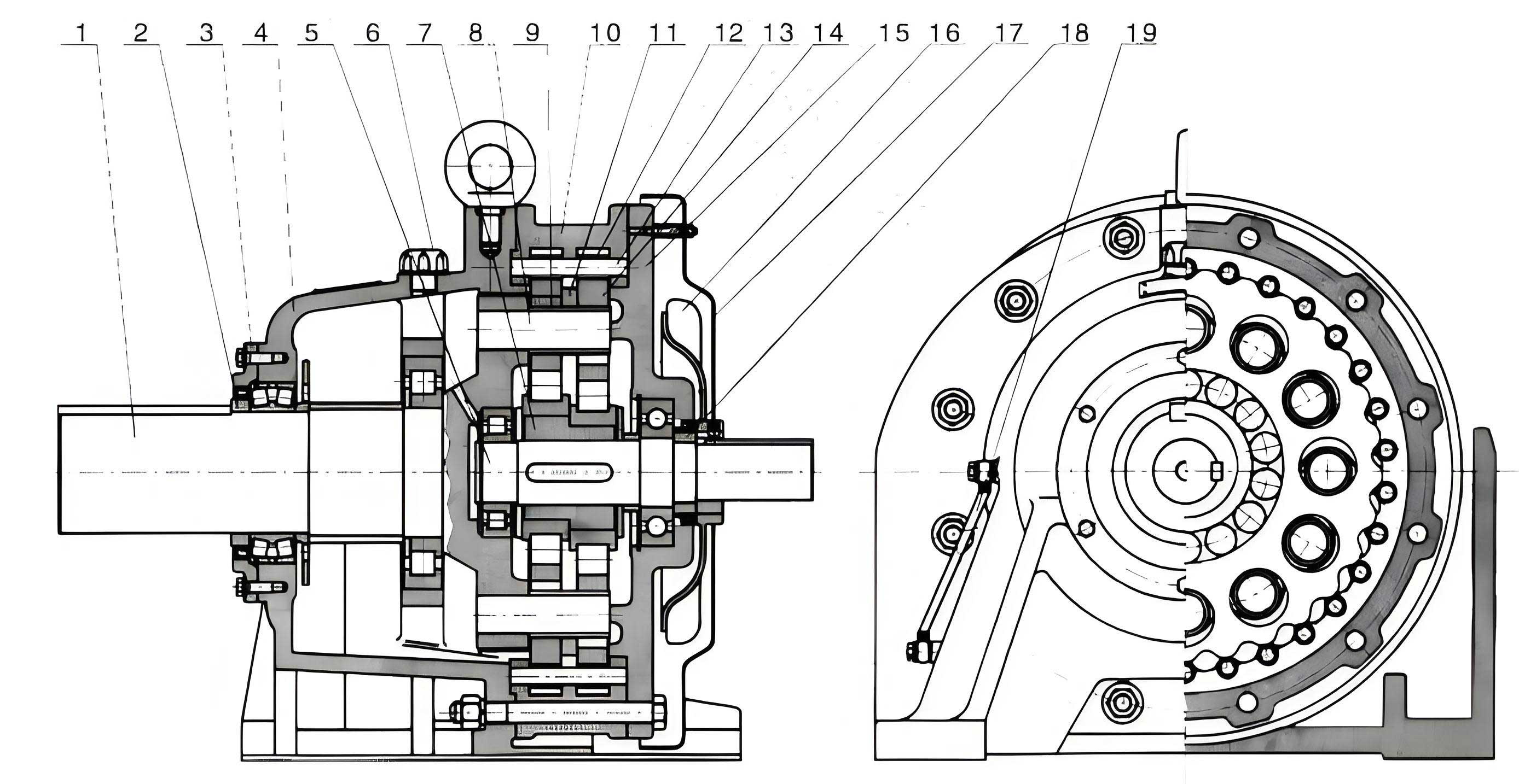
The core functionality of a cycloidal drive hinges on the principle of cycloidal motion within a planetary gear arrangement. I will explain the working mechanism in detail. Fundamentally, a cycloidal drive comprises three main assemblies: the input section, the reduction section, and the output section. The heart of the device is the unique interaction between a cycloidal disk (or disks) and a ring of stationary pins. The input shaft incorporates a dual eccentric cam assembly, often offset by 180°, which houses roller bearings—these form the H-type crank mechanism. The cycloidal disk, mounted on these eccentric bearings, meshes with the stationary pin gear. The tooth profile of the cycloidal disk is generated based on a hypocycloidal or epicycloidal curve, ensuring multi-tooth engagement for high torque capacity and smooth motion.
The mathematical foundation of the cycloidal disk profile is critical. For a standard cycloidal drive using an epitrochoid curve relative to the pins, the coordinates of a point on the cycloidal curve can be described parametrically. Let \( R_p \) be the pitch circle radius of the pin gear, \( R_c \) be the generating circle radius, and \( Z_p \) be the number of pins (or teeth on the pin gear). The parametric equations for the cycloidal disk lobe are often given by:
$$ x = (R_p – R_c) \cos \theta + R_c \cos\left(\left(1 – \frac{Z_p}{Z_c}\right) \theta \right) $$
$$ y = (R_p – R_c) \sin \theta – R_c \sin\left(\left(1 – \frac{Z_p}{Z_c}\right) \theta \right) $$
Here, \( Z_c \) is the number of lobes on the cycloidal disk, typically \( Z_c = Z_p – 1 \). This difference of one tooth is what creates the high reduction ratio. During operation, as the input shaft rotates the eccentric cam one full revolution, the cycloidal disk undergoes a compound motion: it orbits (revolves) around the center and simultaneously rotates (spins) in the opposite direction due to the constraint of the pins. The net rotation of the cycloidal disk per input revolution is a mere \( \frac{1}{Z_p} \) of a revolution. This slow rotation is then extracted by an output mechanism, often a set of pins or rollers in a carrier connected to the output shaft. The theoretical speed reduction ratio \( i \) for a single-stage cycloidal drive is given by:
$$ i = -\frac{Z_p}{Z_p – Z_c} $$
Since \( Z_c = Z_p – 1 \) commonly, this simplifies to \( i = Z_p \). The negative sign indicates direction reversal, which is typically corrected within the drive assembly. For instance, a cycloidal drive with 40 pins will have a reduction ratio of 40:1. This fundamental principle allows the cycloidal drive to achieve high ratios in a compact space. The following table summarizes key kinematic relationships in a standard cycloidal drive.
| Parameter | Symbol | Formula/Relationship | Typical Value Example |
|---|---|---|---|
| Number of Pin Gear Teeth | \( Z_p \) | Fixed design parameter | 40 |
| Number of Cycloidal Disk Lobes | \( Z_c \) | \( Z_c = Z_p – 1 \) | 39 |
| Speed Reduction Ratio | \( i \) | \( i = Z_p \) (for \( Z_c = Z_p – 1 \)) | 40 |
| Input Speed (RPM) | \( N_{in} \) | Given | 1800 RPM |
| Output Speed (RPM) | \( N_{out} \) | \( N_{out} = N_{in} / i \) | 45 RPM |
| Eccentricity (mm) | \( e \) | Design parameter, critical for meshing | 2.5 mm |
Understanding this theory is paramount for effective troubleshooting. In my practice, I have encountered several recurrent failure modes in cycloidal drives. Prolonged continuous operation or frequent start-stop cycles often lead to mechanical wear. A common issue is damage to the keyways on the eccentric cam shaft or the output pinion shaft. The stress concentration in these areas can cause deformation or shear. The standard remedy is to replace the damaged eccentric cam assembly with an identical component from the original manufacturer to ensure dimensional compatibility. As an alternative, I have sometimes employed a machining repair: creating a new keyway at a symmetric position 180° from the damaged one, provided the shaft material integrity is sufficient. The material selection for such repairs is crucial; using a lower-grade material can precipitate premature failure.
Another frequent point of failure is the bearing system, particularly the roller bearings on the eccentric cam (the “rotating arm” bearings). Inadequate lubrication is a primary culprit here. If the lubricant quality deteriorates or the oil level drops, these bearings suffer from increased friction, leading to pitting, spalling, or complete seizure. Similarly, the pin bushings (or needle rollers) on the stationary pin gear can wear out, especially if the drive is subjected to shock loads or overloads beyond its rated capacity. Replacing these requires meticulous attention. It is imperative to use replacement parts from the same manufacturer, as subtle differences in pin diameter, hardness, or surface finish can drastically affect the meshing action and load distribution across the cycloidal disk lobes. To aid in diagnosis, I have compiled a table of common cycloidal drive faults, their symptoms, and recommended actions.
| Common Fault | Primary Symptoms | Potential Causes | Recommended Handling Measures |
|---|---|---|---|
| Eccentric Cam Keyway Damage | Abrupt torque loss, knocking sounds, misalignment | Frequent starts/stops; overload; material fatigue | Replace eccentric cam assembly or machine a new keyway symmetrically. |
| Output Shaft Keyway Wear | Output slippage, irregular motion | High cyclic loads; poor key fit | Replace output shaft or repair keyway; ensure proper key sizing. |
| Rotating Arm Bearing Failure | Increased temperature, grinding noise, vibration | Insufficient or degraded lubrication; contamination; overloading | Immediately stop operation. Replace all rotating arm bearings. Flush housing. |
| Pin Bushing Wear/Damage | Metallic debris in oil, increased backlash, uneven operation | Abrasive wear from contaminants; shock loads; misalignment | Replace complete set of pin bushings. Inspect cycloidal disk for damage. |
| Cycloidal Disk Lobe Scoring | Visible scratches on lobes, efficiency drop | Lack of lubrication; foreign particles; improper assembly | Polish minor scoring if shallow; replace disk for deep damage. Find root cause. |
| Seal Leakage | Oil leaks around input/output shafts | Seal aging, wear, or damage from shaft roughness | Replace shaft seals. Check shaft surface finish for grooves. |
Preventive maintenance is the most effective strategy to avoid these failures and ensure the longevity of a cycloidal drive. I advocate for a rigorous, scheduled maintenance regime tailored to the operational environment. The cornerstone of this regime is lubrication management. For a new cycloidal drive, the initial lubricant should be changed after the first 100 hours of cumulative operation. This first change removes any wear-in particles from manufacturing and initial run-in. The procedure must be thorough: drain the old oil completely, clean the internal housing with a flushing oil if necessary, and remove any residual metallic particles or sludge. Only then should new, recommended-grade lubricant be added. The subsequent oil change interval depends heavily on duty cycle. For a cycloidal drive operating in an 8-hour daily shift under clean, moderate conditions, a 6-month interval is typical. However, in harsh environments—such as those with high dust, moisture, or temperature extremes—or for continuous 24/7 operation, I recommend shortening the interval to as little as 3 months. The table below provides a guideline for lubrication intervals based on service conditions.
| Service Condition Class | Operational Description | Recommended Oil Change Interval | Suggested Lubricant Type (Example) |
|---|---|---|---|
| Light Duty | Clean environment, 8 hr/day, <70% rated load, stable temperature | Every 6 months or 2500 hours | ISO VG 68 or 100 Synthetic Industrial Gear Oil |
| Normal Duty | Moderate dust, 16 hr/day, 70-90% load, some temperature variation | Every 4 months or 2000 hours | ISO VG 150 Extreme Pressure (EP) Gear Oil |
| Heavy Duty / Severe | High contamination, 24/7 operation, >90% load, high ambient temperature or moisture | Every 3 months or 1000 hours | ISO VG 220 Synthetic EP Gear Oil with anti-wear additives |
During oil changes, I always verify the oil level precisely, as both under-filling and over-filling can be detrimental. Over-filling can cause churning and overheating, while under-filling leads to inadequate lubrication and accelerated wear. The ideal level is typically at the center of the sight glass or between the marked lines on the dipstick. Furthermore, the act of refilling must be done in a clean area to prevent introducing dust or other contaminants that could act as abrasives within the precision components of the cycloidal drive.
Beyond lubrication, regular mechanical inspections are vital. I perform periodic checks on the coupling alignment between the cycloidal drive and the connected motor or load. Misalignment generates non-torsional forces (radial and axial loads) that the cycloidal drive bearings are not designed to handle, leading to premature failure. Using a dial indicator, I ensure the parallel and angular alignment is within the manufacturer’s tolerance, often specified as less than 0.05 mm for radial and less than 0.1 mm for axial misalignment. The foundation and mounting bolts are another critical check point. Vibration from long-term operation can loosen these bolts. I tighten all mounting and foundation bolts to the specified torque during scheduled maintenance. Loose foundation bolts can cause the entire unit to shift, creating severe misalignment and potentially catastrophic failure.
Temperature and acoustic monitoring are powerful diagnostic tools. In my routine checks, I use an infrared thermometer to measure the housing temperature of the cycloidal drive during normal operation. A sudden spike or a steady temperature exceeding 70°C (158°F) indicates a problem, such as internal friction from bearing failure, inadequate lubrication, or overload. Similarly, I listen for abnormal noises. A healthy cycloidal drive produces a smooth, subdued hum. The emergence of grinding, clicking, or periodic knocking sounds suggests issues with bearings, pins, or the cycloidal disk itself. For instance, a rhythmic knock might indicate a damaged lobe on the cycloidal disk meshing with the pins.
When component replacement becomes necessary, proper technique is essential to avoid collateral damage. For example, removing a worn eccentric bearing requires care. I always use two pry bars placed symmetrically at the bearing’s mid-section and apply balanced force to ease it out. Applying force from one side or using impact tools might dislodge the bearing but risks damaging the adjacent eccentric cam surface or the housing bore. This philosophy of balanced, methodical force application extends to all disassembly and reassembly procedures for the cycloidal drive.
The compact design of the cycloidal drive, while advantageous for space saving, results in a dense and complex internal architecture. This complexity elevates the skill requirement for maintenance personnel. In my view, only technicians with proven experience or certified training should perform major disassembly or repair on a cycloidal drive. Incorrect assembly—such as improper phase alignment of dual cycloidal disks, incorrect bearing preload, or mismatched components—can induce immediate failure or significantly reduce the drive’s lifespan. Therefore, investing in proper training for maintenance staff is as important as the physical maintenance acts themselves.
Moreover, I emphasize the need for a condition-based maintenance approach. This involves keeping detailed logs for each cycloidal drive unit. The log should record operation hours, load profiles, lubrication history, temperature trends, and any anomalous sounds or vibrations observed. By analyzing this data over time, I can often identify patterns that signal the onset of a fault before it causes downtime. For example, a gradual, steady increase in operating temperature might indicate progressive bearing wear, allowing for planned intervention during a scheduled shutdown rather than an emergency repair.
To systematize this, I recommend implementing a simple fault预警 mechanism. This can be as straightforward as setting thresholds for temperature and vibration. Mounting a temperature sensor with an alarm set at 75°C and a vibration sensor on the housing can provide early warnings. When thresholds are exceeded, the system alerts the maintenance team to investigate. This proactive strategy minimizes unplanned downtime and allows for corrective action when repair costs are still low. The mathematical basis for such monitoring can involve trend analysis. For instance, if we measure housing temperature \( T(t) \) over time \( t \), a concerning trend might be a positive slope \( \frac{dT}{dt} \) exceeding a certain limit during steady-state operation, which can be modeled as:
$$ \frac{dT}{dt} > k \quad \text{(for a sustained period)} $$
Here, \( k \) is an empirical constant determined from historical healthy operation data for that specific cycloidal drive model and duty cycle. Similarly, vibration amplitude \( A(f) \) at characteristic frequencies \( f \) related to bearing or gear mesh can be monitored. An increase in amplitude at the bearing defect frequency \( f_{bd} \), calculated from bearing geometry and speed, signals bearing deterioration.
In conclusion, the reliability and longevity of a cycloidal drive are not merely a function of its inherent design quality but are profoundly influenced by the care it receives throughout its service life. From my perspective, a comprehensive maintenance program for a cycloidal drive must be multi-faceted, encompassing strict lubrication schedules, precise alignment checks, diligent bolt tightening, sensory monitoring (temperature and sound), and meticulous record-keeping. The complex internal mechanics demand skilled attention, and the maintenance strategy must be adapted to the specific operating environment—whether it’s a clean robotic cell or a dusty mining conveyor. By embracing these practices, we can fully harness the advantages of the cycloidal drive: its high reduction ratio, compactness, and robustness. Ultimately, a well-maintained cycloidal drive is a key asset, providing reliable power transmission that safeguards overall operational efficiency and productivity for countless industrial applications. The continued evolution of monitoring technologies will only enhance our ability to care for these ingenious mechanical systems, ensuring they perform optimally for years to come.