Abstract
This study investigates the contact fatigue crack propagation mechanisms in cylindrical gears with variable hyperbolic circular-arc-tooth-trace (VH-CATT). By establishing numerical models for contact ellipse analysis and employing extended finite element method (XFEM), the crack initiation sites, propagation paths, and stress intensity factors (SIFs) under varying design parameters (modulus, tooth line radius, torque) are systematically explored. Results indicate that larger gear modulus increases SIFs in both tooth width and core directions during long crack propagation, while larger tooth line radii effectively reduce SIFs. Pre-set crack angles also significantly influence crack trajectories and SIF magnitudes. This work provides critical insights for optimizing VH-CATT cylindrical gear design to enhance fatigue resistance and operational reliability.

1. Introduction
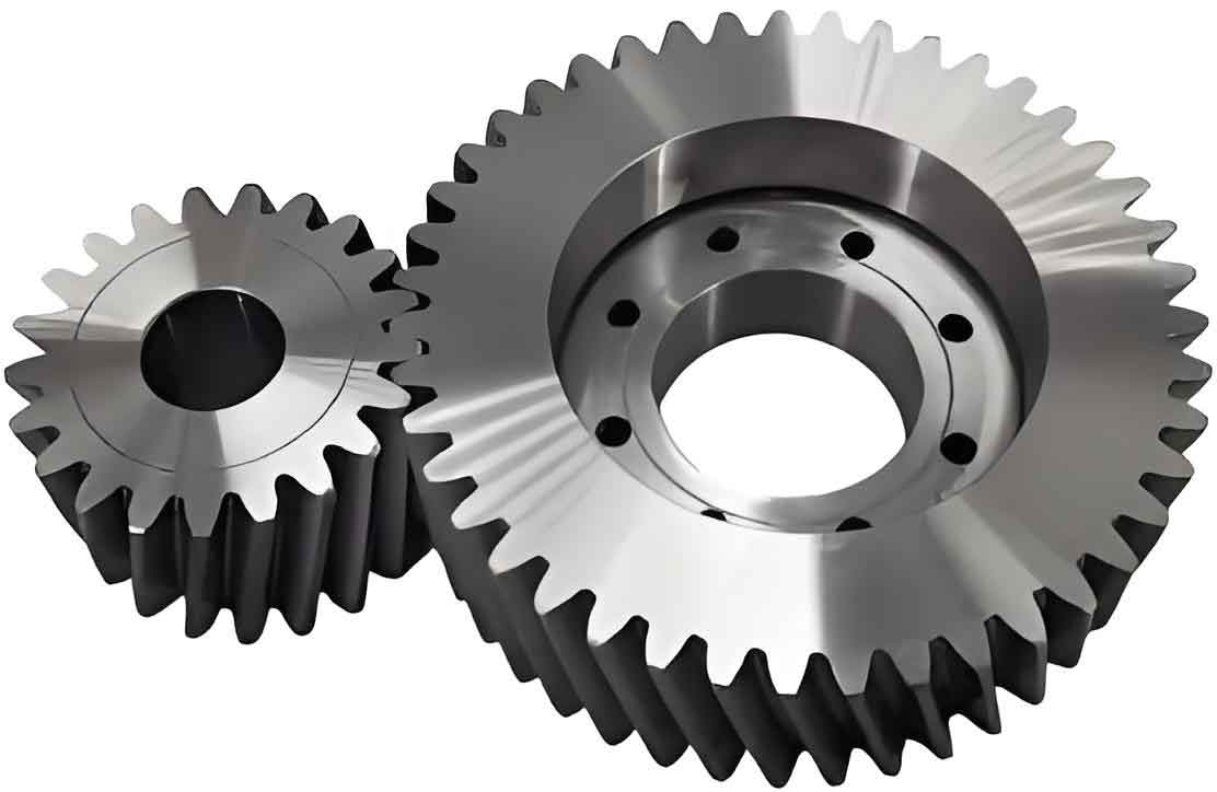
Cylindrical gears are pivotal components in mechanical transmission systems, yet contact fatigue cracks severely compromise their reliability and lifespan. Fatigue failure typically initiates from micro-cracks, progressing through stages of initiation, propagation, and final fracture. For cylindrical gears with variable hyperbolic circular-arc-tooth-trace (VH-CATT), unique geometric features such as point contact and hybrid curvature profiles necessitate specialized studies to understand crack behavior under cyclic loading.
Common failure modes of cylindrical gears, including pitting, spalling, and tooth fracture. Unlike conventional spur or helical gears, VH-CATT cylindrical gears exhibit superior load capacity, meshing efficiency, and reduced axial forces. However, their complex curvature characteristics amplify challenges in predicting crack propagation paths and stress concentrations.
This study bridges this gap by integrating XFEM simulations with fracture mechanics to analyze crack dynamics in VH-CATT cylindrical gears. Key contributions include:
- Development of a numerical model for contact ellipse trajectory prediction.
- Quantitative evaluation of design parameters on crack propagation rates.
- Stress intensity factor (SIF) analysis for crack front optimization.
2. Theoretical Analysis of VH-CATT Cylindrical Gears
2.1 Forming Principle
VH-CATT cylindrical gears are machined using a dual-blade milling process. The rotating cutter head generates hyperbolic tooth traces, while the gear blank undergoes synchronized rotational and translational motions. The resulting tooth profile combines a mid-section involute with variable hyperbolic curves, enabling high-performance meshing.
2.2 Tooth Surface Equations
The mathematical model of the VH-CATT cylindrical gear tooth surface is derived through coordinate transformations between the cutter and workpiece. Key equations include:
- Working Tooth Surface:{xdi=[−Acosθi+RT+Riφi]cosφi+(uicosα−Ri)sinφiydi=[Acosθi−RT−Riφi]sinφi+(uicosα−Ri)cosφizdi=Asinθi⎩⎨⎧xdi=[−Acosθi+RT+Riφi]cosφi+(uicosα−Ri)sinφiydi=[Acosθi−RT−Riφi]sinφi+(uicosα−Ri)cosφizdi=Asinθiwhere A=τuisinα+RT±π4mA=τuisinα+RT±4πm.
- Transition Tooth Surface:β=arctan[hj∗mcosθi−rsinαcosθi±Bicosθiτ(Riφi+RT)−rcosαcosθi]β=arctan[±Bicosθiτ(Riφi+RT)−rcosαcosθihj∗mcosθi−rsinαcosθi]
2.3 Contact Ellipse Determination
The contact ellipse dimensions (long axis aa, short axis bb) are calculated using Hertzian contact theory:{a=ka3ω2E(A+B)3b=kb3ω2E(A+B)3⎩⎨⎧a=ka32E(A+B)3ωb=kb32E(A+B)3ω
where ωω is the applied load, EE is the equivalent elastic modulus, and ka,kbka,kb are ellipticity coefficients.
Table 1 summarizes the design parameters of the VH-CATT cylindrical gear pair used in simulations.
| Parameter | Driving Gear | Driven Gear |
|---|---|---|
| Number of Teeth | 21 | 29 |
| Modulus (mm) | 4 | 4 |
| Tooth Line Radius (mm) | 200 | 200 |
| Pressure Angle (°) | 20 | 20 |
| Elastic Modulus (GPa) | 210 | 210 |
| Poisson’s Ratio | 0.3 | 0.3 |
3. Finite Element Simulation of Crack Propagation
3.1 XFEM Methodology
The extended finite element method (XFEM) enables crack propagation modeling without remeshing. The displacement approximation incorporates enrichment functions:uh(X)=∑i=1NNi(X)ui+∑j=1SNj(X)Hj(X)aj+∑k=1TNk(X)∑q=14Φq(X)bqkuh(X)=i=1∑NNi(X)ui+j=1∑SNj(X)Hj(X)aj+k=1∑TNk(X)q=1∑4Φq(X)bqk
where H(X)H(X) and Φq(X)Φq(X) represent crack surface and tip enrichments, respectively.
3.2 Crack Initiation and Propagation
Pre-set semi-circular cracks (radius = 0.2 mm) were introduced at high-stress regions identified via contact ellipse analysis. Cyclic torque (140–360 N·m) was applied to simulate operational loading.
4. Results and Discussion
4.1 Crack Propagation Trajectories
Cracks initially propagated symmetrically toward the gear core, then diverged toward tooth ends. The final fracture angle relative to the tooth surface was ~50°, consistent with spur gear behavior.
4.2 Effect of Tooth Line Radius
Table 2 compares crack growth rates under varying tooth line radii (RTRT). Larger RTRT reduced crack speed in the tooth width direction but increased it in the core direction.
| Tooth Line Radius (mm) | Crack Speed (Width) | Crack Speed (Core) |
|---|---|---|
| 100 | 0.25 mm/cycle | 0.18 mm/cycle |
| 200 | 0.20 mm/cycle | 0.22 mm/cycle |
| 300 | 0.15 mm/cycle | 0.25 mm/cycle |
4.3 Effect of Modulus
Larger modulus (mm) increased crack propagation rates in both directions (Table 3).
| Modulus (mm) | Crack Speed (Width) | Crack Speed (Core) |
|---|---|---|
| 1.5 | 0.10 mm/cycle | 0.08 mm/cycle |
| 3.0 | 0.15 mm/cycle | 0.12 mm/cycle |
| 5.0 | 0.30 mm/cycle | 0.25 mm/cycle |
4.4 Stress Intensity Factor Analysis
SIF trends during crack growth. Mode-I SIF dominated in long-crack stages, while Mode-II and III contributions diminished.
Key Findings:
- Larger modulus increased SIFs in both directions.
- Pre-set angles >90° delayed initial crack growth but amplified SIFs in later stages.
5. Conclusions
- Critical Crack Sites: Single-tooth engagement zones near the pitch circle are high-risk regions for crack initiation.
- Design Optimization: Increasing tooth line radius (RTRT) reduces SIFs during long-crack propagation, while modulus adjustments balance crack speed and stress distribution.
- Simulation Accuracy: XFEM combined with fracture mechanics reliably predicts crack trajectories and SIFs, aiding fatigue life estimation.
