

Since the large hypoid gear wheel is processed by forming method, the profile of the hypoid gear wheel tooth surface is exactly the same as that of the cutter head. According to the machining coordinate system of the large hypoid gear wheel established in the figure, after a series of coordinate transformations, The cutting surface equation of the hypoid gear wheel can be transformed into the fixed coordinate system S2 of the hypoid gear wheel through a series of coordinates. At this time, in the fixed coordinate system S2 of hypoid gear wheel, the radial vector and normal vector of the reference point can be obtained as follows:

Where, the coordinate transformation matrix MMG from cutter head coordinate system SG to machine tool fixed coordinate system SM is:

The coordinate transformation matrix M2M from the machine tool fixed coordinate system SM to the large wheel fixed coordinate system S2 of hypoid gear with small number of teeth and large reduction ratio is:

LMG and l2m are the 3×3 order matrix obtained by removing the last row and the last column of MMG and M2M respectively.
Substitute the formula to obtain:

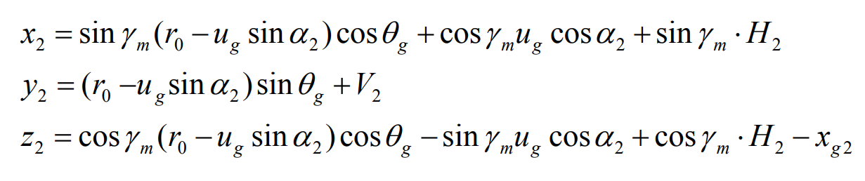
Multiply the right formula to obtain the gear tooth surface equation of hypoid gear:
Replace the 3×3 order matrix obtained by removing the last row and the last column of MMG and M2M into the formula to obtain:

The normal of the gear tooth can be multiplied by the right hypoid equation:
