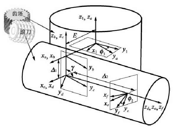
Worm or hob machining helical gear coordinate system is shown in the figure, S1 is worm or hob coordinate system, SF is gear blank coordinate system, SA is rack coordinate system, and the rest are auxiliary coordinate system. In the process of gear grinding or hobbing of diagonal worm, the hob rotates around its own axis, and the gear blank rotates around its own axis; in addition, the hob feeds along the tooth blank axially and feeds diagonally along the tooth blank. The combination of the two movements forms a diagonal hobbing, which can reduce the roughness of the tooth surface, make the tooth wear evenly, and improve the service life and durability of the cutter 。
The results show that the rotation relationship between hob and gear blank is as follows:

C is the diagonal feed coefficient, and the relationship between the axial feed of hob and the diagonal feed displacement is linear

Where, N1 is the number of hob teeth; N2 is the number of teeth of the gear blank; β 1 is the spiral angle of the hob; β 2 is the spiral angle of the gear blank; ϕ 2 is the rotation angle of the gear blank; ϕ 3 is the rotation angle of the gear blank; Δ 1 is the axial feed displacement of the hob along the tooth blank; Δ 2 is the diagonal feed displacement of the hob along the gear blank; R1 is the dividing circle radius of the gear blank; R2 is the dividing circle radius of the gear blank.

Its installation parameters are

Where E0 is the center distance between hob and gear blank, and γ is the installation angle of hob.
In order to realize the traditional method of machining helical gear, the center distance change between hob and gear is added. A is the conversion coefficient of center distance, which can be calculated by the maximum modification amount

According to the position relationship of worm grinding or hobbing, the point vector RF and normal vector NF of helical gear tooth surface are obtained as follows

Where R1 (L1, L2) is the tool point vector; N1 (L1, L2) is the tool normal vector; RF (L1, L2, U2, Δ 1) is the helical gear point vector; NF (L1, L2, U2, Δ 1) is the helical gear normal vector; MF1 (ϕ 2, Δ 1) is the coordinate transformation matrix from S1 to SF; LF1 (ϕ 2, Δ 1) is the vector transformation matrix from S1 to SF.
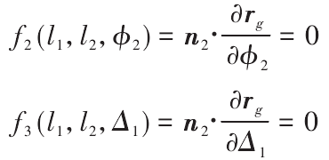
According to the meshing principle, there are two independent movements in the grinding or hobbing process of the worm, one is the rotation of the cutter and the tooth blank, the other is the axial feed and diagonal feed of the cutter, so the tooth surface equation should satisfy the independent meshing equation, which is solved by differential geometry

The equation of tooth surface can be obtained by the simultaneous formula.
