Aviation gear transmission is developing towards high speed and heavy load. As the core component of various power devices, the meshing performance of helical gear transmission has attracted people’s attention. Therefore, in the design of helical gear transmission, more and more optimization design methods have emerged and are widely used.
After more than half a century of rapid development, gear tooth modification has become a core technology for reducing helical gear vibration and improving system transmission stability, and is widely used in high-speed helical gear transmission systems such as aviation aircraft, engines, and helicopter reducers. At present, tooth profile modification is mainly divided into two methods: tooth profile modification and tooth orientation modification. The interference part in the contact of the helical gear pair is correspondingly removed, which is called tooth profile modification. A pair of helical gear pairs can either perform tooth top modification on two helical gears separately, or only modify the tooth top and root of one of the helical gears. This modification method can alleviate the changes in the meshing stiffness of the helical gear pair, thereby reducing the impact of tooth meshing in and out caused by factors such as base section machining errors and elastic deformation under load, and improving the lubrication state of the tooth surface. During the transmission process, under the action of load, the transmission system will produce elastic deformation, including tooth bending deformation, shear deformation, and contact deformation. At the same time, the supporting shaft will also produce bending deformation and torsional deformation. The combined effect of these deformations will cause distortion of the helical line of the tooth, resulting in uneven load distribution along one end of the tooth, that is, biased load phenomenon.
Performing tooth profile modification on helical gears can eliminate the uneven distribution of load in the tooth width direction, improve the phenomenon of off load, and enhance the bearing capacity of helical gears. With the rapid development of computer technology, a large number of designers and scholars use KISSsoft software to optimize the design and related analysis of helical gears. KISSsoft software is a specialized transmission system design and analysis software, which has strong calculation and simulation capabilities and parameter optimization analysis functions in the field of helical gear design. By using KISSsoft software to modify the tooth profile and direction of the helical gears in aircraft engine reducers, design costs can be saved and the development cycle can be shortened.
ZHY Gear used KISSsoft software to perform a modification design analysis on the helical gear of an aviation reducer. The results showed that appropriate modification of the helical gear can improve its load-bearing capacity and meshing performance. By comparing with the actual meshing marks of helical gears, the reliability of the KISSsoft software analysis results has been verified, providing a reference for the modification design of helical gears.
1. Optimization evaluation indicators for helical gear modification
1.1 Helical Gear tooth strength
The failure modes of helical gears mainly include four types: tooth surface pitting, tooth breakage, tooth surface wear, and plastic deformation. In order to improve the reliability of the helical gear transmission in aircraft engine reducers, it is necessary to conduct force analysis and strength verification to analyze whether the helical gear transmission meets the service life requirements.
Among them, considering the contact strength of the tooth surface to avoid pitting failure is one of the important indicators for evaluating whether the helical gear pair meets the life requirements. Tooth surface pitting refers to the pitting damage caused by fatigue of the helical gear material under cyclic contact stress. This pattern mainly occurs in closed helical gears with good lubrication, and the helical gears of aircraft engine reducers belong to this category; The bending strength of the tooth root reflects the bending resistance of helical gears, which refers to the maximum stress that helical gears can withstand when the tooth root fractures or the material reaches the specified bending moment under the action of bending load.
1.2 Transmission error
Manufacturing errors, assembly errors, and elastic deformation caused by tooth loading can cause the driven gear to not rotate synchronously and uniformly with the driving gear during the helical gear transmission process. This asynchronous rotation is called transmission error. In theory, the meshing position of the driving gear profile A and the driven gear profile is at position B. However, due to the asynchronous rotation caused by the above factors, the actual position of the driven gear profile is at position B ‘, and the driving gear must rotate by an additional angle δ Only then can the correct meshing position be reached. The length of point A on the driving gear moving along the meshing line to B ‘is the transmission error, as shown in Figure 1.
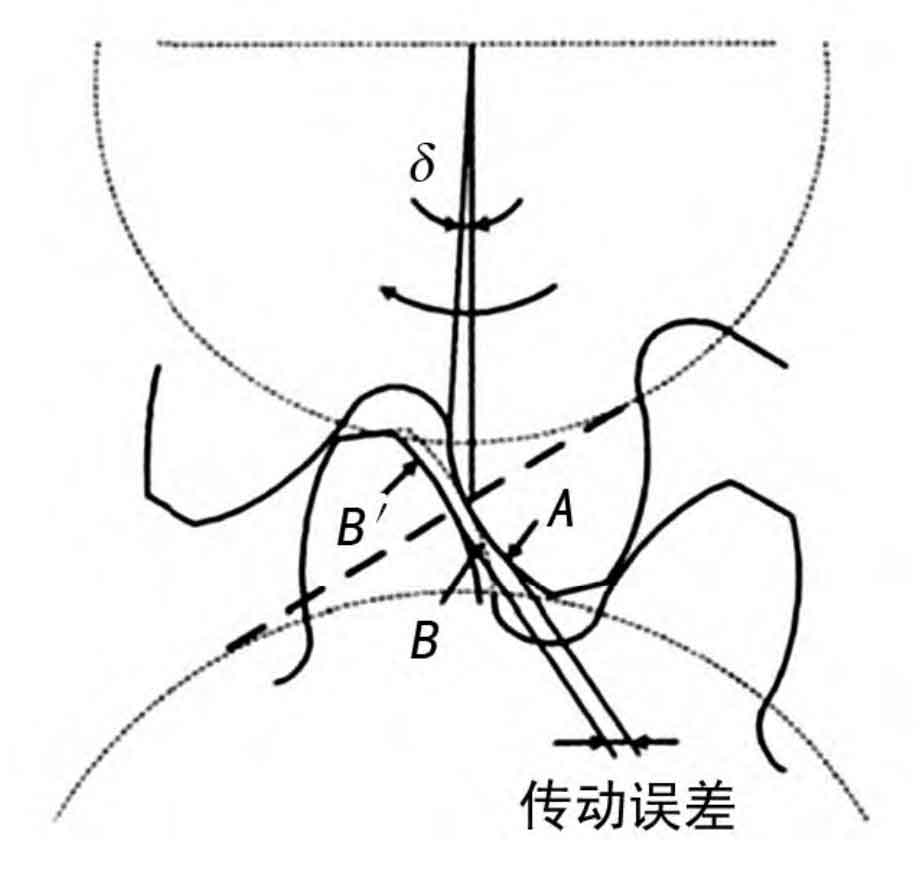
Transmission error is an important indicator for evaluating the dynamic performance of helical gear transmission process, and is a parameter that describes the smoothness of helical gear transmission systems. The smaller the absolute peak to peak value of transmission error, the smoother the operation of the helical gear system during transmission.
1.3 Distribution of tooth surface load
The tooth stress curve is a curve that describes the distribution of load on the gear pair during the meshing process of helical gears. In the helical gear transmission system, due to manufacturing errors, installation errors, and deformation under load, a pair of helical gear pairs will experience uneven load distribution, stress concentration, and sudden load changes during meshing, weakening the bearing capacity of the helical gear. Therefore, in order to meet the service life requirements of helical gears, it is necessary to effectively control the load distribution on the tooth surface, eliminate sudden changes in tooth surface load, eccentric load, and concentrated tooth end load, in order to improve the bearing capacity of helical gears.
1.4 Sliding rate
The sliding rate can affect the non steady state effect of helical gear elastohydrodynamic lubrication, which is an important factor determining the degree of wear of helical gears, and directly affects the magnitude and direction of friction torque between helical gear pairs. In order to improve the anti pitting and anti wear capabilities of the helical gear transmission system, while ensuring that the degree of tooth root wear of a pair of helical gears is similar, it is necessary to limit the magnitude of the sliding rate and try to balance the sliding rate between the two gears of the helical gear pair as much as possible: the sliding rate is between -1 and 1, indicating the optimal working state of the gears; The sliding rate is between -2 and 2, indicating that the helical gear is in good working condition.
2. KISSsoft software for helical gear profile modification design
2.1 Basic parameters of gear teeth
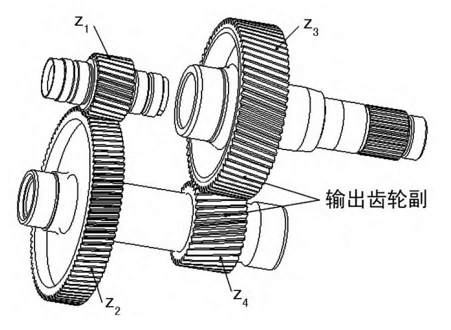
The study focuses on a pair of helical gear pairs in a certain aircraft engine reducer, and the structural diagram is shown in Figure 2. Z1, z2, z3, and z4 are all helical gears, with z1 and z2 as input helical gear pairs and z3 and z4 as output helical gear pairs. The input power is 250 kW and the input speed is 42000 r/min. The output helical gear pair is selected as the research object in the article, and the basic parameters of the gear teeth are listed in Table 1.
| Name | Middle double gear: small gear z3 | Output gear z4 |
| Normal modulus mn/mm | 1.75 | 1.75 |
| Number of teeth Z | 33 | 67 |
| Normal pressure angle α/ (°) | 22.5 | 22.5 |
| Spiral angle β / (°) | 12.7 | 12.7 |
| Rotation direction | Left-handed rotation | Right-handed rotation |
| Tooth width B/mm | 37 | 33 |
| Accuracy level | HB0-91-1998, | Level 5 accuracy |
2.2 Design of shape modification plan
According to ISO standards, the formula for tooth profile modification is:

In the formula: Δ Max is the maximum amount of shape correction; ξ A is the end face overlap; KA is the operating condition coefficient; Ft/b is the circumferential force per unit tooth width; C γ Calculate the meshing stiffness of the helical gear. The formula for tooth profile modification is:

In the formula, Ca represents the amount of modification; F β Xcv represents the original meshing tooth alignment error. KISSsoft software automatically provides reference for profile modification based on international standards, taking into account factors such as transmission error, flash temperature, and tooth surface load distribution of helical gear systems.
| Parameter | Tooth profile modification amount/ μM | Tooth profile modification starting point dca/mm | Tooth alignment modification and drum shape modification amount/ μM |
| Z3 | 7 | φ 60.519 | 8 |
| Z4 | 7 | φ 117.352 | 8 |
Calculate the modification amount based on reference standards, combined with model experience, and based on the transmission error curve and tooth surface stress distribution obtained from contact analysis, select a set of most effective modification parameters, as listed in Table 2.
2.3 Result Analysis
The strength verification of the gear teeth was carried out using ISO 6336: 2006 method B. The calculation results of the load-bearing capacity of the front and rear teeth before and after the modification are shown in Table 3.
| Parameters | Z3 | Z4 |
| Contact stress of tooth surface before modification/MPa | 1 064.93 | 1 064.93 |
| Bending stress of tooth root before modification/MPa | 420.15 | 466.32 |
| Dynamic load coefficient KV before shaping | 1.5030 | 1.5030 |
| Distribution coefficient of contact tooth load before modification KHβ | 1.081 1 | 1.081 1 |
| Contact stress on tooth surface after modification/MPa | 1 012.88 | 1 012.88 |
| Bending stress of tooth root after modification/MPa | 379.34 | 421.02 |
| Modified dynamic load coefficient KV | 1.337 8 | 1.337 8 |
| Distribution coefficient of contact tooth load after modification KHβ | 1.098 7 | 1.098 7 |
From Table 3, it can be seen that the dynamic load coefficient decreases after the modification, indicating a smoother gear transmission. But the distribution coefficient of tooth load increases, because tooth profile modification is beneficial for offsetting the misalignment of gear teeth and reducing the distribution coefficient of tooth load; On the other hand, it will reduce the tooth contact width and increase the tooth load distribution coefficient, so the influence of tooth profile modification on the tooth load distribution coefficient is uncertain. Overall, the contact stress on the tooth surface and the bending stress at the tooth root of the modified helical gear are reduced, which improves the load-bearing capacity of the gear teeth.
The transmission error of helical gears is an important indicator reflecting the dynamic performance during the meshing process of helical gears. The transmission error curves of the gears before and after modification are shown in Figure 3.
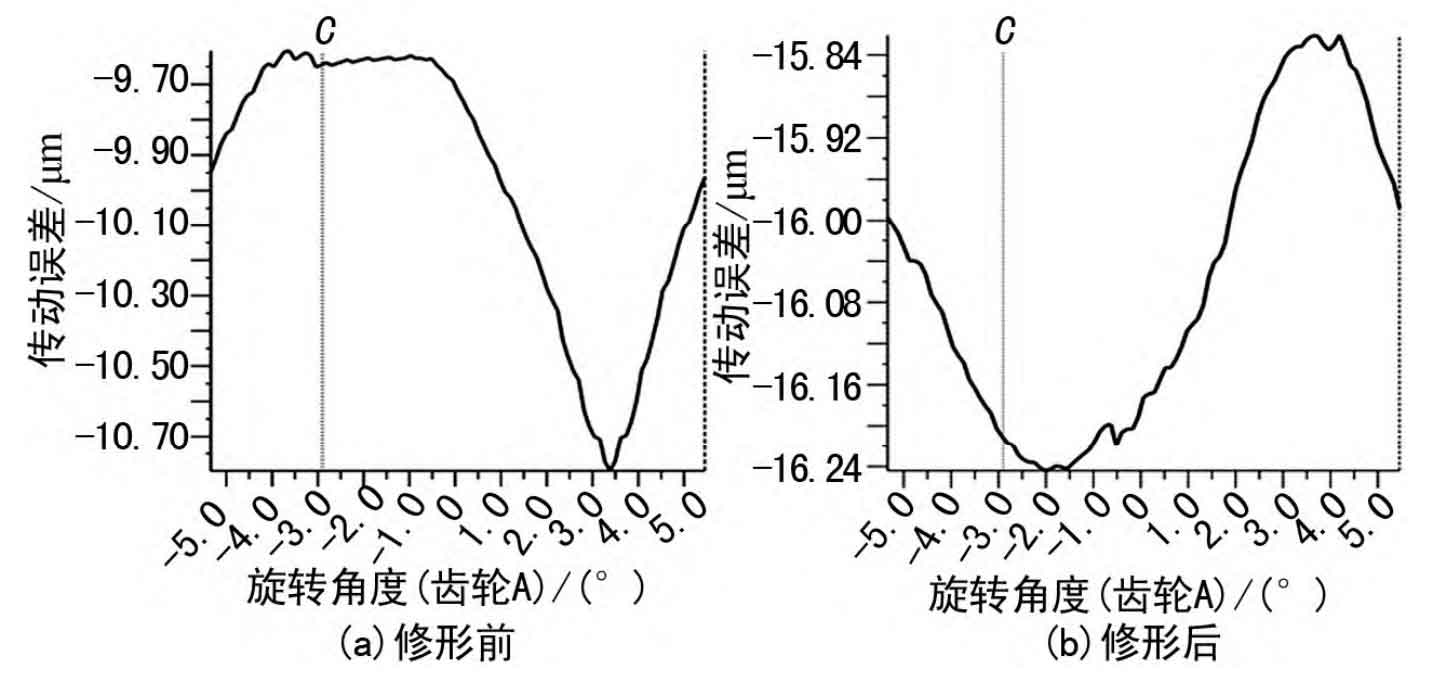
From Figure 3, it can be seen that the fluctuation range of the transmission error curve before shaping is relatively large, ranging from -10.80 to -9.61 μ m. After shaping, the curve fluctuates less, decreasing from -16.24 to -15.82 μ m. The peak value has decreased slightly; The transmission error is 1.19 before the modification μ Reduce m to 0.42 μ m. This indicates that shaping can make the operation of helical gear transmission process smoother, which is beneficial for improving noise and vibration phenomena.
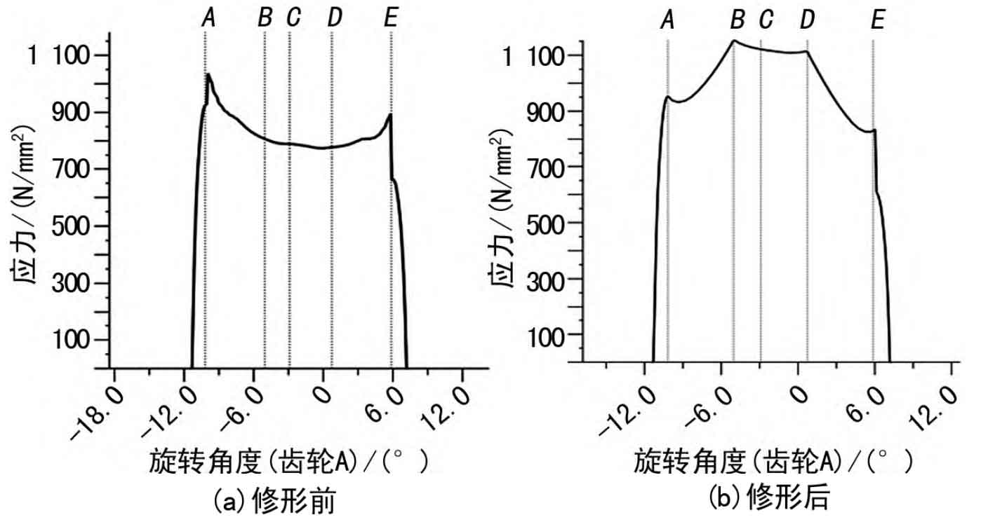
In the helical gear transmission system of aircraft engine reducers, the damage of the helical gear tooth surface is a common form of failure. The main reason is the edge contact generated during the meshing process of the helical gear, which causes local stress to exceed the material yield limit, resulting in the helical gear bonding until local peeling occurs on the tooth surface. Figures 4 and 5 show the stress curve and distribution of contact spots on the tooth surface, respectively.

From Figure 4 (a) and Figure 5 (a), it can be seen that the load distribution on the tooth surface of the helical gear before modification is uneven, and there is a large load near the tooth top and root, with a maximum load of 1180.9 N/mm, indicating a more severe phenomenon of load deviation; In addition, there is a sudden change in load along the meshing line, which may cause significant additional dynamic loads and be detrimental to the meshing of helical gears during the transmission process. After the modification, the load on the tooth surface of the gear teeth extends outward from the middle and is concentrated in the middle of the tooth width. The boundary effect is eliminated, and the maximum load is reduced to 1153.4 N/mm. The overall load is reduced, and the load distribution near the tooth top and root is relatively small (see Figure 4 (b) and Figure 5 (b)), effectively reducing excessive wear on the tooth top and root.
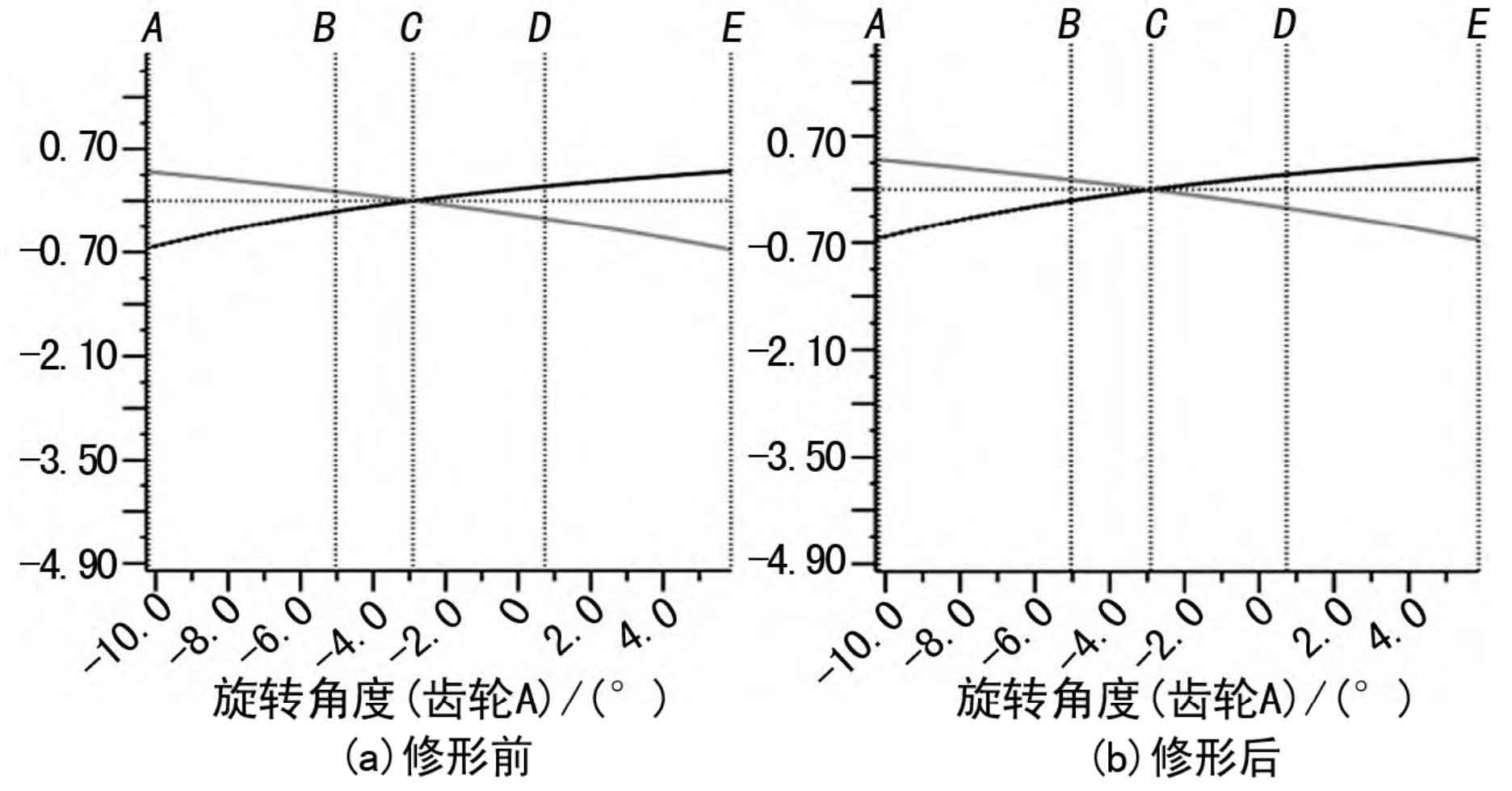
In the design of helical gears, it is advisable to balance the sliding rate of the two gears as much as possible, mainly to ensure that the wear degree of the large and small gears is similar during the transmission process. Using KISSsoft software to analyze the sliding rate curve of the gear pair before and after practice, the results are shown in Figure 6. From Figure 6, it can be seen that there is little change in the sliding rate of the helical gear before and after modification, both within the range of -1 to 1.
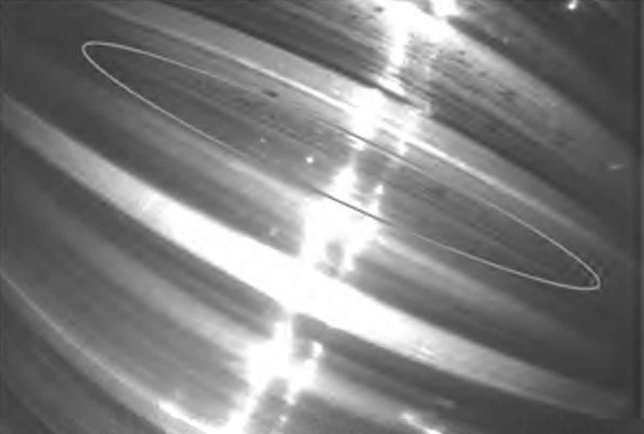
After the modification according to the modification plan, the contact marks on the tooth surface of the aviation reducer after engine testing are shown in Figure 7. The results show that the actual contact imprints on the tooth surface are concentrated in the middle of the tooth width, consistent with the KISSsoft analysis results (Figure 5 (b)). This indicates that effective tooth profile modification parameters can be obtained using KISS soft, eliminating the tedious calculation process; The load distribution on the tooth surface analyzed by the software is consistent with the actual situation, which shortens the development cycle.
3. Conclusion
ZHY Gear used KISS soft software to perform a modification design analysis on a certain aviation reducer helical gear. By comparing and analyzing the tooth strength, transmission error, tooth surface load distribution, and sliding rate before and after modification, it was demonstrated that tooth modification can effectively improve the transmission performance of helical gears. Finally, the analysis results were compared with the actual contact marks of helical gears. The specific results are as follows.
(1) By appropriate shaping, the tooth surface stress and tooth root stress of the reducer helical gear can be reduced, and the load-bearing capacity of the helical gear can be improved.
(2) Helical gear modification can effectively reduce transmission errors during the helical gear transmission process, making the transmission system operate more smoothly, and is beneficial for reducing noise and vibration.
After modification, the load distribution on the tooth surface becomes more uniform, avoiding sudden load changes and improving the fatigue strength and service life of helical gears.
(4) After the aviation reducer was tested with the engine, the contact marks on the helical gear were consistent with the results of KISS soft analysis, indicating that effective tooth surface modification parameters can be obtained using KISS soft to achieve the modification goal.
