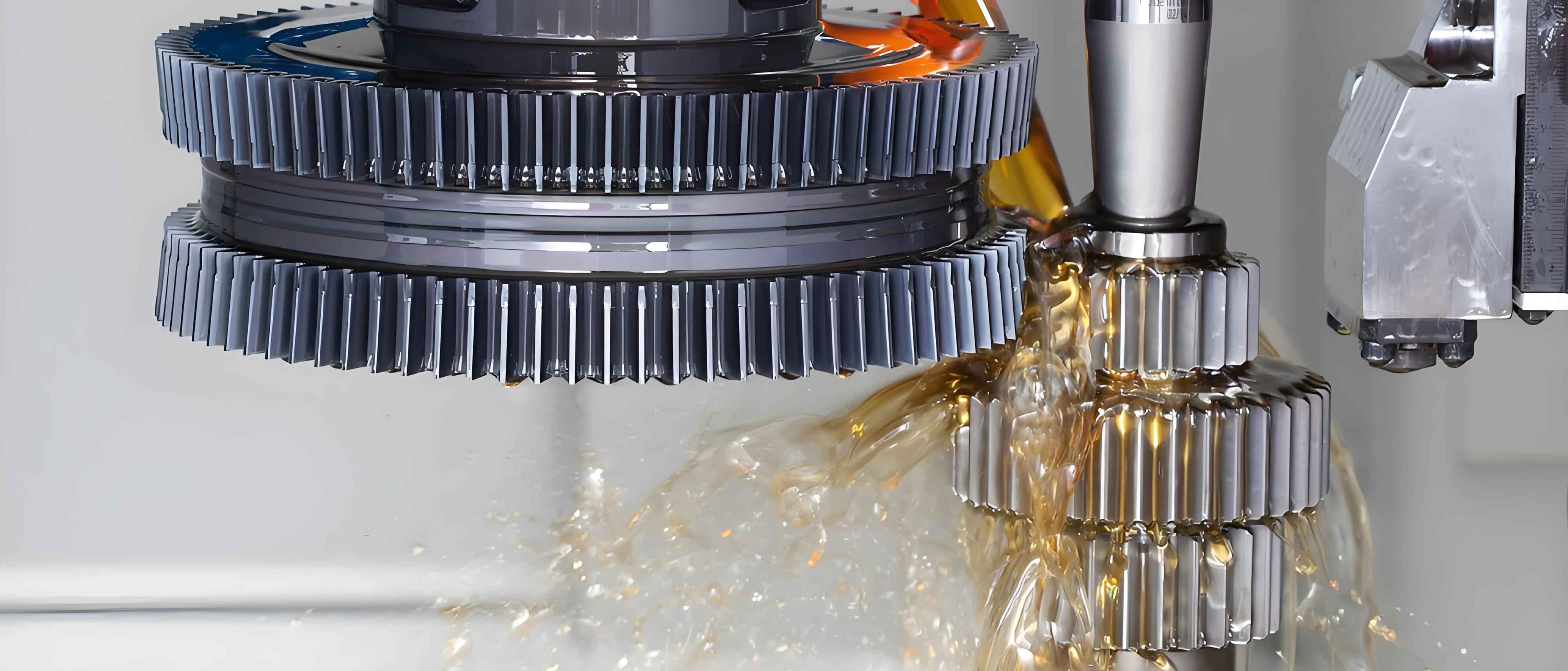
Continuous advancements in mechanical processing demand higher precision in component manufacturing. High-precision equipment is essential for modern industrial production, where CNC technology enhances automation and intelligence while minimizing machining errors. As CNC machinery replaces traditional equipment, limitations emerge in large-scale gear shaping applications. Conventional crank-slider mechanisms in large CNC gear shaping machines exhibit uneven cutting speeds—slower at entry/exit points and insufficient force at the center—hindering market demands. Hydraulic main drive systems effectively address these challenges, enabling efficient machining of large gears.
Gear shaping utilizes the generating method for tooth formation. A specialized cutter, geometrically identical to the target gear, performs cutting via reciprocating motion along the workpiece axis. Synchronized rotation between cutter and workpiece (generating motion) forms the gear profile through successive passes. Infeed motion radially advances the cutter incrementally to full depth, preventing tool damage. Multiple infeed cycles may be applied for hardened materials or deep teeth, governed by:
$$n_i = \left\lceil \frac{h}{d_{max}} \right\rceil$$
where \(n_i\) is infeed cycles, \(h\) is full tooth depth, and \(d_{max}\) is maximum permissible infeed per cycle based on tool/workpiece properties.
Functional requirements for large-scale CNC gear shaping systems include:
| Parameter | Value | Description |
|---|---|---|
| Max Cutting Length | 600 mm | Effective reciprocating stroke |
| Min Cutting Length | 60 mm | Minimum reciprocating stroke |
| Max Cutting Force | 36.42 kN | Calculated for tool module=20, depth=15mm |
| Cutting Speed | 10 m/min | Optimal for gear shaping quality |
| Upstroke Speed | 25 m/min | Non-cutting return speed |
| Downstroke Speed | 12.5 m/min | Cutting stroke speed |
Cutting force derivation considers shear stress (\(\tau\) = 3137 MPa) and cutting area (\(A_c\) = 11.61 mm²):
$$F_c = A_c \times \tau$$
Hydraulic asymmetry necessitates a 2:1 downstroke-to-upstroke time ratio to balance flow dynamics. Position sensing resolution must achieve 0.005 mm, with pressure sensors in both cylinder chambers.

Motion scheme selection prioritizes hydraulic drives over crank-sliders. Traditional systems exhibit sinusoidal velocity profiles causing uneven cutting forces:
$$v_{crank} = \omega r \left( \sin\theta + \frac{r \sin 2\theta}{2l} \right)$$
where \(\omega\) is angular velocity, \(r\) is crank radius, \(l\) is connecting rod length, and \(\theta\) is rotation angle. Hydraulic systems enable programmable velocity control and eliminate mechanical inertia limitations.
The hydraulic drive integrates proportional valves, accumulators, and cartridge valves to achieve:
- Stepless speed regulation
- Position holding at any stroke point
- Dynamic braking during emergencies
Flow continuity equation for asymmetric cylinders:
$$A_d v_d = A_u v_u$$
where \(A_d\)/\(A_u\) are downstroke/upstroke piston areas, and \(v_d\)/\(v_u\) are velocities. Area ratio compensation maintains force consistency throughout the gear shaping cycle.
Generating motion synchronizes cutter/workpiece rotation via worm gear reducers and servo motors. The transmission ratio \(i_g\) follows:
$$i_g = \frac{z_w}{z_g}$$
where \(z_w\) is worm threads and \(z_g\) is gear teeth. Infeed motion uses ball screws with step resolution:
$$\Delta x = \frac{p}{R}$$
for screw pitch \(p\) and reduction ratio \(R\).
Technical specifications for large-scale gear shaping machines include:
| Parameter | Value |
|---|---|
| Max Workpiece Diameter | 1600 mm |
| Max Module | 16 mm |
| Max Tooth Width | 380 mm |
| Stroke Rate | 10-60 str/min |
| Radial Feed Rate | 0-500 mm/min |
Spindle mechanical design addresses three subsystems:
- Main Motion: Hydraulic cylinder diameter \(D\) derives from force equilibrium:
$$D = \sqrt{\frac{4F_c}{\pi p \eta}}$$
for pressure \(p\) and efficiency \(\eta\). Length accommodates 650mm stroke plus infeed allowance. - Generating Motion: Worm gear sizing follows torque requirements:
$$T_g = F_c \times r_p$$
where \(r_p\) is pitch radius. - Tool Retraction: Optimized for minimal inertial mass during high-frequency disengagement.
Spindle strength verification considers alternating bending stresses. Safety factor \(n\) must satisfy:
$$n = \frac{\sigma_{end}}{\sigma_{eq}} \geq 2.5$$
where \(\sigma_{end}\) = 525 MPa (bending endurance limit) and equivalent stress \(\sigma_{eq}\) combines bending/torsional components:
$$\sigma_{eq} = \sqrt{ \left( \frac{32M_f}{\pi d^3} \right)^2 + 3 \left( \frac{16T}{\pi d^3} \right)^2 }$$
for bending moment \(M_f\), torque \(T\), and spindle diameter \(d\).
In conclusion, hydraulic main drives resolve critical limitations in large-scale CNC gear shaping. By enabling programmable velocity profiles, high torque output, and position-controlled infeed, they ensure consistent cutting forces across the entire stroke. This system enhances gear shaping precision for modules up to 16mm and diameters exceeding 1600mm, meeting evolving industrial demands.
