
In the realm of precision engineering, the demand for compact and efficient power transmission systems has driven significant innovation in gear design. As a researcher focused on advanced gear manufacturing, I have dedicated considerable effort to exploring hypoid gears with high reduction ratios, particularly those with minimal pinion teeth counts. These gears are pivotal in applications such as robotics, servo systems, and integrated electromechanical devices, where high power density and smooth operation are paramount. This article delves into the design methodology, geometric constraints, and gear cutting processes for hypoid gears with ratios as extreme as 3:60, presenting a comprehensive analysis from theoretical foundations to practical validation. The integration of gear cutting techniques throughout the development cycle is essential to achieve functional prototypes, and I will emphasize this aspect repeatedly to underscore its importance in manufacturing.
The design of hypoid gears with high reduction ratios involves intricate geometric considerations, especially when the pinion tooth count is reduced to as few as three teeth. Traditional design rules, such as those outlined by the American Gear Manufacturers Association (AGMA), typically recommend a minimum of five teeth for the pinion and a sum of pinion and gear teeth exceeding 40. However, pushing beyond these limits requires a meticulous approach to avoid issues like tooth undercutting, excessive axial forces, and poor meshing characteristics. My work focuses on overcoming these challenges through optimized pitch cone determination and careful selection of tooth geometry parameters. The core of this design lies in establishing appropriate pitch cones for both the pinion and gear, which directly influence the gear’s performance and manufacturability. In the following sections, I will outline the geometric constraints, introduce a novel convergence condition for pitch cone design, detail the tooth geometry calculations, and present results from three-dimensional simulations and actual gear cutting experiments. Throughout, the role of gear cutting in validating designs will be highlighted, as it is the critical step that transforms theoretical models into tangible components.
Geometric Constraints in Pitch Cone Design
When designing hypoid gears with a high reduction ratio, the first step is to define the pitch cones for the pinion and gear. This process is governed by several geometric constraints that ensure proper meshing, avoid interference, and maintain strength balance. From my perspective, these constraints must be rigorously applied to prevent failures in both operation and manufacturing. Below, I summarize the key constraints that guided my design for a 3:60 hypoid gear pair.
The limitation on the second kind of meshing boundary point is crucial to prevent undesirable tooth contact phenomena. To avoid this, the limiting pressure angle must be controlled. The formula for the limiting pressure angle is given by:
$$ \tan \alpha_{\text{lim}} = \frac{R_2 \sin \beta_2 – R_1 \sin \beta_1}{R_2 \tan \delta_2 + R_1 \tan \delta_1} \cdot \frac{\cos \epsilon’}{\tan \delta_1 \tan \delta_2} $$
Here, \( \alpha_{\text{lim}} \) is the limiting pressure angle, \( R_1 \) and \( R_2 \) are the pitch radii at the midpoint for the pinion and gear respectively, \( \beta_1 \) and \( \beta_2 \) are the spiral angles, \( \delta_1 \) and \( \delta_2 \) are the pitch cone angles, and \( \epsilon’ \) is the shaft angle minus the difference in spiral angles (\( \epsilon’ = \beta_1 – \beta_2 \)). In my design, I constrained \( \alpha_{\text{lim}} < 8^\circ \) to ensure smooth meshing without boundary point issues.
Another traditional constraint involves the limiting curvature radius, which historically was set equal to the cutter radius to achieve symmetric meshing properties. The limiting curvature radius \( r_{\text{lim}} \) is calculated as:
$$ r_{\text{lim}} = \frac{\tan \beta_1 – \tan \beta_2}{\frac{1}{R_1 \cos \beta_1} – \frac{1}{R_2 \cos \beta_2} – \tan \alpha_{\text{lim}} \left( \frac{\tan \beta_1}{R_1 \tan \delta_1} + \frac{\tan \beta_2}{R_2 \tan \delta_2} \right)} $$
For high-reduction ratio designs, I relaxed this constraint, requiring only that the ratio \( r_{\text{lim}} / r_c \) be within 1% of unity, where \( r_c \) is the cutter radius. This flexibility allows for non-symmetric designs that can enhance strength on the working side, a modern approach that deviates from classical norms.
Manufacturing constraints also play a significant role. As the gear reduction ratio increases, the gear pitch cone angle \( \delta_2 \) approaches 90°, which can lead to interference between the gear face cone and the cutter during gear cutting. To avoid this, I limited \( \delta_2 \leq 85^\circ \). Additionally, to prevent undercutting of the pinion and ensure balanced strength, the virtual number of teeth for the pinion \( z_{v1} \) must be sufficient. It is computed as:
$$ z_{v1} = \frac{z_1}{\cos \delta_1 \cos^3 \beta_1} $$
In this case, I ensured \( z_{v1} \geq 50 \), even though the actual pinion tooth count is only 3. This constraint helps maintain tooth integrity and facilitates effective gear cutting processes.
Further geometric constraints include the offset ratio and spiral angle limits. The offset distance \( E \) relative to the gear pitch radius \( r_2 \) should satisfy \( 0.3 \leq E / r_2 \leq 0.6 \) to maintain proper hypoid geometry. Moreover, to control axial forces, the gear spiral angle was restricted to \( \beta_2 \leq 40^\circ \). These constraints collectively ensure that the design is feasible for both operation and gear cutting, as excessive axial loads or improper offsets can complicate manufacturing and reduce gear life.
| Constraint | Formula or Condition | Design Value |
|---|---|---|
| Limiting Pressure Angle | \( \alpha_{\text{lim}} < 8^\circ \) | 7.5° (example) |
| Limiting Curvature Radius | \( \left| \frac{r_{\text{lim}}}{r_c} – 1 \right| \leq 0.01 \) | 0.005 (achieved) |
| Gear Pitch Cone Angle | \( \delta_2 \leq 85^\circ \) | 84.945° |
| Pinion Virtual Teeth | \( z_{v1} \geq 50 \) | 52.3 (calculated) |
| Offset Ratio | \( 0.3 \leq E / r_2 \leq 0.6 \) | 0.45 |
| Gear Spiral Angle | \( \beta_2 \leq 40^\circ \) | 36.552° |
Novel Convergence Condition for Pitch Cone Design
In classical hypoid gear design, the pitch cone parameters are determined through a series of fixed conditions that often restrict optimization. For high-reduction ratios, I proposed a new convergence condition that maximizes the pinion volume, thereby enhancing its strength and durability. This approach is particularly relevant when the pinion has very few teeth, as it compensates for potential weakness by increasing its bulk.
The pinion enlargement factor \( k_1 \) is a key metric, defined as:
$$ k_1 = \tan \beta_2 \sin \epsilon’ + \cos \epsilon’ $$
To maximize \( k_1 \), I derived the condition by setting the derivative with respect to \( \epsilon’ \) to zero, yielding \( \epsilon’ = \beta_2 \). Since \( \epsilon’ = \beta_1 – \beta_2 \), this simplifies to \( \beta_1 = 2\beta_2 \). This relationship indicates that when the gear spiral angle \( \beta_2 \) is fixed, setting the pinion spiral angle \( \beta_1 \) to twice that value maximizes the pinion volume. This convergence condition became the objective function in my optimization routine, guiding the selection of pitch cone parameters.
Using this condition, along with the geometric constraints listed earlier, I formulated an optimization problem to solve for the pitch cone parameters: \( \delta_1, \beta_1, t_{z1} \) for the pinion, and \( \delta_2, \beta_2, t_{z2} \) for the gear, where \( t_z \) represents the distance from the pitch cone apex to the crossing point. The optimization was performed using numerical methods in MATLAB, ensuring that all constraints were satisfied while achieving the maximum pinion enlargement factor. This method represents a departure from traditional design tables, allowing for tailored solutions that excel in high-ratio applications. The success of this approach hinges on precise gear cutting to realize the designed geometry, as even minor deviations can compromise the enhanced volume benefits.
Tooth Geometry Design and Parameter Selection
Once the pitch cones are established, the next step is to design the tooth geometry, including tooth height, addendum, dedendum, and root angles. This phase is critical because improper tooth proportions can lead to issues like tooth tip sharpening or inadequate root strength, both of which can be exacerbated during gear cutting. My design philosophy incorporates composite modification—combining radial and tangential shifts—to intentionally increase the pinion outer diameter, thereby improving its load-bearing capacity.
A primary concern is the pinion tooth tip thickness, which must be sufficient to prevent breakage. The formula for the gear cutter tip width \( W_2 \) is used to adjust the pinion tip thickness:
$$ W_2 = s_{n1} – h_{f2} (\tan \alpha_u – \tan \alpha_v) $$
where \( s_{n1} \) is the pinion normal chordal thickness at the midpoint, \( h_{f2} \) is the gear dedendum, and \( \alpha_u, \alpha_v \) are the pressure angles on the left and right flanks. The pinion normal thickness is given by \( s_{n1} = p_n \cos \beta_2 – s_{n2} \), with \( s_{n2} = 0.5 p_n \cos \beta_2 – (h_{a1} – h_{a2}) \tan \alpha – k_t m_n \). Here, \( p_n = \pi m_n \) is the normal circular pitch, \( m_n \) is the normal module, \( h_{a1}, h_{a2} \) are addendums, \( \alpha \) is the mean pressure angle, and \( k_t \) is the tooth thickness coefficient. The pinion tip thickness \( S^*_{an} \) is then computed as:
$$ S^*_{an} = r_{a1} \left( \frac{s_{n1}}{r_1} – (\text{inv} \alpha_{au} – \text{inv} \alpha_u) – (\text{inv} \alpha_{av} – \text{inv} \alpha_v) \right) $$
I ensured that \( S^*_{an} \geq 0.4 m_n \) to maintain robustness, a standard that directly influences gear cutting tool selection and feed rates.
Another vital aspect is the minimum tooth space width at the pinion inner end, which affects cutter clearance and chip evacuation during gear cutting. The formula is:
$$ W_{L1} = p_{in} – (h_{fi1} + h_{fi2}) (\tan \alpha_u – \tan \alpha_v) + j_{\text{min}} $$
where \( p_{in} = 2\pi \cos \beta_i / z_2 \cdot R_i \sin \delta_2 \) is the normal circular pitch at the inner end, \( h_{fi1}, h_{fi2} \) are dedendums at the inner end, and \( j_{\text{min}} \) is the minimum backlash. I constrained \( W_{L1} \geq 0.4 m_n \) to ensure adequate space for cutting tools, which is essential for achieving smooth gear cutting operations without tool damage.
These tooth geometry considerations are integral to the overall design, as they dictate the feasibility of gear cutting processes. For instance, selecting appropriate addendum coefficients and tooth thickness modifications requires balancing theoretical ideals with practical machining limits. In my design for the 3:60 hypoid gear, I iteratively adjusted these parameters using MATLAB scripts until both tooth tip thickness and space width criteria were met. This iterative process underscores the synergy between design and gear cutting, where each parameter adjustment must be evaluated for its manufacturability.
| Parameter | Pinion | Gear |
|---|---|---|
| Number of Teeth | 3 | 60 |
| Normal Module (midpoint) \( m_n \) | 1.5 mm | 1.5 mm |
| Addendum Coefficient | 0.8 | 0.6 |
| Dedendum Coefficient | 1.0 | 1.2 |
| Tooth Thickness Coefficient \( k_t \) | 0.1 | -0.05 |
| Tip Thickness \( S^*_{an} \) | 0.65 mm (≥ 0.4\( m_n \)) | — |
| Minimum Space Width \( W_{L1} \) | 0.72 mm (≥ 0.4\( m_n \)) | — |
Calculation of Geometric Parameters
The calculation of geometric parameters follows a systematic approach, starting with basic input values and proceeding through pitch cone optimization and tooth geometry refinement. For the 3:60 hypoid gear pair, I began by specifying the fundamental parameters: pinion teeth \( z_1 = 3 \), gear teeth \( z_2 = 60 \), gear pitch radius \( r_2 = 60 \) mm, shaft angle \( \Sigma = 90^\circ \), offset distance \( E = 27 \) mm, and cutter radius \( r_c = 100 \) mm. These values were chosen based on structural requirements and prior experience in gear cutting for similar applications.
Using the optimization framework described earlier, I solved for the pitch cone parameters. The results were: pinion pitch cone angle \( \delta_1 = 4.070^\circ \), spiral angle \( \beta_1 = 73.000^\circ \), and apex distance \( t_{z1} = 15.2 \) mm; gear pitch cone angle \( \delta_2 = 84.945^\circ \), spiral angle \( \beta_2 = 36.552^\circ \), and apex distance \( t_{z2} = 58.7 \) mm. These values satisfied all geometric constraints and maximized the pinion enlargement factor, demonstrating the effectiveness of the novel convergence condition.
Next, I computed the tooth geometry parameters, including addendum, dedendum, working depth, and root angles. The calculations incorporated composite modification to boost the pinion outer diameter. Key results include a pinion outer diameter of 22.198 mm and a gear outer diameter of 119.906 mm. The contact ratio was calculated to be 5.854, indicating smooth and continuous meshing—a desirable trait for high-reduction gears. All computations were automated in MATLAB, ensuring accuracy and repeatability. This computational phase is crucial before proceeding to gear cutting, as it provides the blueprint for manufacturing.
The table below summarizes the final geometric parameters for both the pinion and gear. These parameters served as the input for subsequent three-dimensional modeling and gear cutting trials.
| Parameter | Pinion | Gear |
|---|---|---|
| Number of Teeth | 3 | 60 |
| Pitch Cone Angle | 4.070° | 84.945° |
| Spiral Angle (midpoint) | 73.000° | 36.552° |
| Face Cone Angle | 6.307° | 84.486° |
| Root Cone Angle | 4.443° | 82.191° |
| Outer Diameter | 22.198 mm | 119.906 mm |
| Whole Depth (outer end) | 3.114 mm | 3.070 mm |
| Midpoint Normal Tooth Thickness | -0.975 mm (modified) | — |
| Contact Ratio | 5.854 | |
Three-Dimensional Simulation and Gear Cutting Validation
With the geometric parameters finalized, I proceeded to create three-dimensional models to visualize the gear teeth and assess their form. This step is vital for detecting potential issues like tooth distortion or interference before actual gear cutting, saving time and resources. I used MATLAB to generate discrete coordinate points for the tooth surfaces based on the derived geometry. These points were then imported into UG (now Siemens NX) software to construct solid models.
For the gear with 60 teeth, a forming cutting method was employed in the simulation due to its large pitch cone angle (close to 90°), which makes it resemble a crown gear. The theoretical tooth profile approximates a straight line, simplifying the modeling process. The pinion model was generated via envelope simulation using the gear model, incorporating minor modifications of a few microns to account for practical gear cutting adjustments. The resulting models confirmed that the pinion with only three teeth did not exhibit abnormal distortion, validating the suitability of the selected spiral angles and modification coefficients. This outcome is significant because it demonstrates the feasibility of extreme reduction ratios without compromising tooth integrity, a key consideration for gear cutting applications in compact spaces.
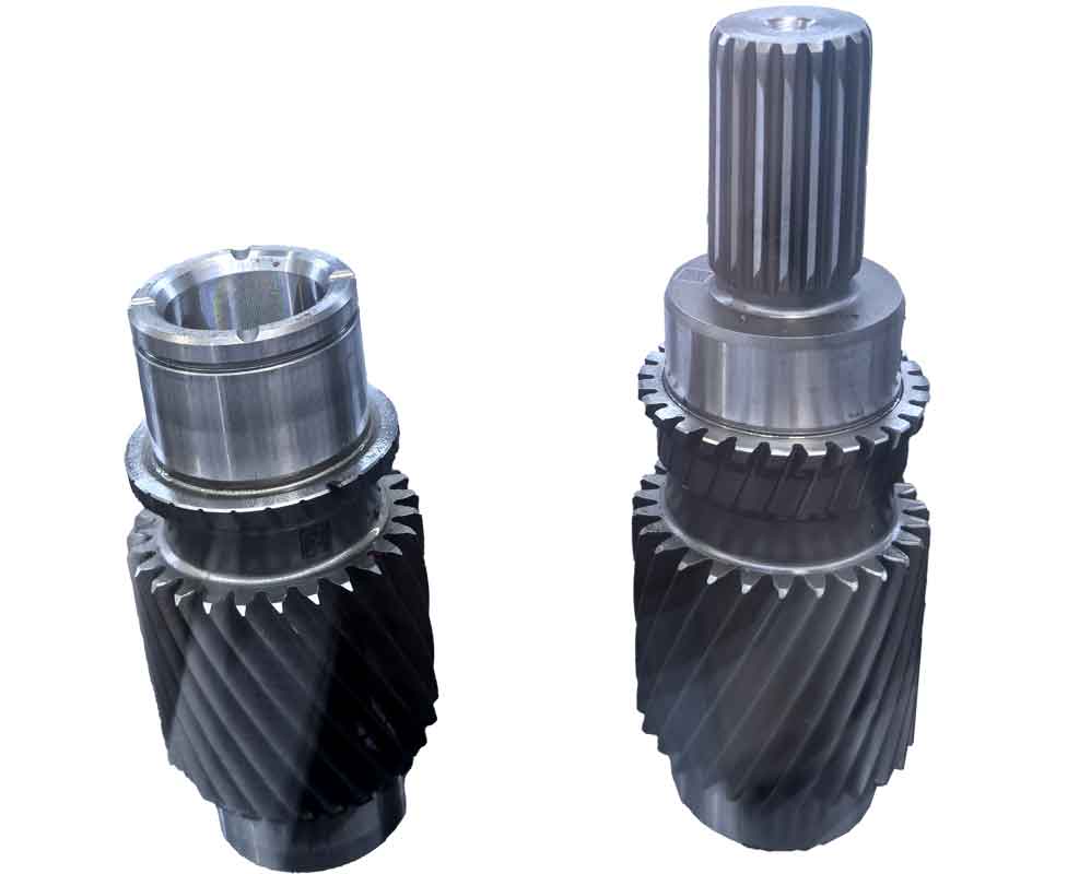
The image above illustrates a hypoid gear pair similar to the one designed in this study, showcasing the complex tooth geometry achievable through advanced gear cutting techniques. While this is a generic representation, it highlights the importance of precision in manufacturing such components.
Following the simulation, I conducted actual gear cutting trials on a GH-35 hypoid gear milling machine to transform the virtual designs into physical parts. The gear was cut using a forming method, which proved feasible without interference between the gear face cone and the cutter, thanks to the \( \delta_2 \leq 85^\circ \) constraint. The pinion, with its small module, was cut using a conventional duplex method (double-sided cutting) with standard gear cutting tools. The process required careful adjustment of machine settings to accommodate the unique geometry, particularly the high spiral angle and minimal tooth count.
The cut gears matched the three-dimensional models in shape, confirming the accuracy of the design and the effectiveness of the gear cutting process. However, due to the small size of the prototype and the focus on tooth form validation, rolling contact tests were deferred for future work. Nonetheless, the successful gear cutting of both components underscores the practical viability of 3:60 hypoid gears for high-reduction applications. This achievement highlights the critical role of gear cutting in bridging design and reality, as even the most sophisticated designs must be manufacturable to be useful.
Discussion on Design and Manufacturing Implications
The design and gear cutting of high-reduction ratio hypoid gears present several implications for both theory and practice. From a theoretical standpoint, the novel convergence condition based on maximizing pinion volume offers a new optimization criterion that can be applied to other gear types. This approach challenges traditional symmetric design paradigms, allowing for tailored solutions that enhance performance in specific applications. The mathematical formulation, involving constraints on pressure angles, curvature radii, and tooth geometry, provides a framework that can be extended to even higher ratios or different materials.
In terms of manufacturing, the gear cutting process for such gears requires meticulous attention to tool selection, feed rates, and machine calibration. The use of forming cutting for the gear and duplex cutting for the pinion proved effective, but further refinements could involve multi-axis CNC gear cutting for improved accuracy. Additionally, the small module and high spiral angle necessitate specialized cutters and cooling strategies to prevent tool wear and ensure surface finish. These considerations are essential for scaling up production, where repeatability and efficiency in gear cutting become paramount.
Another aspect worth discussing is the trade-off between design flexibility and manufacturability. While composite modification allows for increased pinion outer diameter, it also complicates the gear cutting process by requiring non-standard tool paths. Future work could explore adaptive gear cutting techniques that dynamically adjust parameters based on real-time feedback, further enhancing precision. Moreover, the integration of simulation tools like UG with gear cutting machines could streamline the transition from design to production, reducing lead times and costs.
The table below contrasts key aspects of traditional versus the proposed design and gear cutting approach for high-reduction hypoid gears.
| Aspect | Traditional Design | Proposed Design with Novel Convergence |
|---|---|---|
| Pinion Tooth Count | ≥ 5 | As low as 3 |
| Convergence Condition | Limiting curvature radius equals cutter radius | Maximize pinion volume (\( \beta_1 = 2\beta_2 \)) |
| Tooth Symmetry | Symmetric design preferred | Non-symmetric allowed for strength |
| Gear Cutting Method | Standard duplex or form cutting | Adapted forming/duplex with modifications |
| Manufacturing Focus | Adherence to AGMA standards | Optimization for specific applications |
Conclusion and Future Directions
In conclusion, the design and gear cutting of high-reduction ratio hypoid gears with minimal pinion teeth are feasible through careful geometric constraint management and optimized parameter selection. The proposed novel convergence condition, which maximizes pinion volume, provides a robust foundation for pitch cone determination. Coupled with composite tooth modifications, this approach ensures adequate strength and meshing quality even for extreme ratios like 3:60. The three-dimensional simulations and successful gear cutting trials validate the theoretical framework, demonstrating that such gears can be manufactured using existing machinery with minor adjustments.
Looking ahead, several avenues for future research emerge. First, investigating the dynamic performance of these gears under load will be crucial to assess their durability and noise characteristics. This could involve finite element analysis and experimental testing on dedicated rigs. Second, advancing gear cutting technologies—such as implementing grinding for hard-faced teeth or exploring additive manufacturing for prototypes—could further enhance precision and efficiency. Third, extending the design methodology to even higher reduction ratios (e.g., 2:80) or different configurations (e.g., non-orthogonal shafts) would push the boundaries of what is achievable. Throughout these endeavors, the integration of gear cutting as a core consideration will remain essential, as it is the ultimate step that brings innovative designs to life.
Ultimately, this work contributes to the growing body of knowledge on advanced gear systems, offering practical insights for engineers and manufacturers. By embracing optimization and precision gear cutting, we can develop compact, high-performance transmissions that meet the evolving demands of modern technology. The journey from conceptual design to physical gear cutting is a testament to the synergy between theory and practice, a synergy that will continue to drive progress in mechanical engineering.