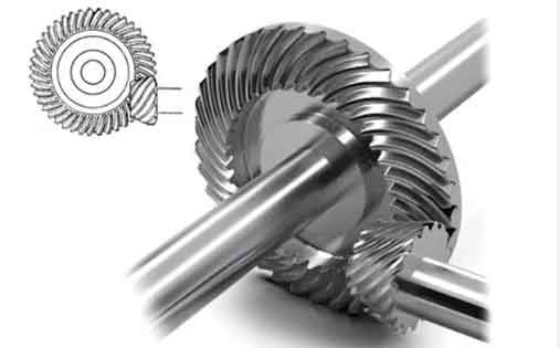
This paper presents a comprehensive investigation into the meshing performance of spiral bevel gears with high contact ratio designs. By optimizing local synthesis parameters and implementing advanced tooth contact analysis methods, two distinct design approaches – inner diagonal contact path and face width-oriented contact path – are systematically compared for their error sensitivity, strength characteristics, and load transmission behavior.
1. Preset Meshing Performance Parameters
The fundamental equations governing tooth contact analysis (TCA) for spiral bevel gears are established as:
$$ \begin{cases}
\mathbf{r}_h^{(1)}(\theta_p, \phi_p, \phi_1) = \mathbf{r}_h^{(2)}(\theta_g, \phi_g, \phi_2) \\
\mathbf{n}_h^{(1)}(\theta_p, \phi_p, \phi_1) = \mathbf{n}_h^{(2)}(\theta_g, \phi_g, \phi_2)
\end{cases} $$
where $\mathbf{r}_h^{(i)}$ and $\mathbf{n}_h^{(i)}$ represent position vectors and unit normal vectors in the fixed coordinate system, respectively. The geometric contact conditions at mesh entry/exit points are defined by:
$$ v_2 – h_{a2} – \tan\theta_{a2}(h_2 – R_{e2}) = 0 \quad \text{(Mesh entry)} $$
$$ v_1 – h_{a1} – \tan\theta_{a1}(h_1 – R_{e1}) = 0 \quad \text{(Mesh exit)} $$
| Parameter | Pinion | Gear |
|---|---|---|
| Number of teeth | 23 | 65 |
| Module (mm) | 3.9 | 3.9 |
| Pressure angle (°) | 25 | 25 |
| Spiral angle (°) | 35 | 35 |
| Face width (mm) | 37 | 37 |

2. High Contact Ratio Design Methodology
The contact ratio $\varepsilon_r$ is calculated as:
$$ \varepsilon_r = \frac{|T_{in} – T_{out}|}{T_{mesh}} $$
For face width-oriented design, the contact path direction angle $\eta_2$ and radial machine setting $\Delta y$ are optimized to achieve:
$$ \varsigma = \frac{|T_{in} – T_0|}{|T_0 – T_{out}|} \approx 1 $$
ensuring symmetric transmission error distribution.
3. Performance Comparison
The loaded tooth contact analysis (LTCA) results under 1000 N·m torque reveal significant performance differences:
| Performance Metric | Inner Diagonal | Face Width | Improvement |
|---|---|---|---|
| Pinion bending stress (MPa) | 110.24 | 95.24 | 13.67% |
| Gear bending stress (MPa) | 127.70 | 114.86 | 10.05% |
| Contact stress (MPa) | 1033.39 | 973.74 | 5.77% |
| LTE amplitude (arcsec) | -13.53 | -9.29 | 31.32% |
4. Error Sensitivity Analysis
The face width-oriented design demonstrates superior tolerance to assembly errors:
$$ \Delta \Sigma = 0.005\,rad,\ \Delta E = 0.5\,mm,\ \Delta A_1 = 0.3\,mm,\ \Delta A_2 = 0.5\,mm $$
Key sensitivity relationships:
$$ S_{\Delta E}^{face} < S_{\Delta \Sigma}^{face} < S_{\Delta A}^{face} $$
$$ S_{\Delta A}^{diag} < S_{\Delta E}^{diag} < S_{\Delta \Sigma}^{diag} $$
5. Conclusion
The face width-oriented high contact ratio design for spiral bevel gears demonstrates:
- Enhanced bending strength (13.67% pinion, 10.05% gear)
- Superior contact strength (5.77% improvement)
- Reduced LTE amplitude (31.32% decrease)
- Improved assembly error tolerance
This design methodology provides significant advantages for high-speed, heavy-duty applications of spiral bevel gears in aerospace and precision transmission systems.
