
As a researcher dedicated to advancing industrial robotics, I recognize the critical role of precision reducers in ensuring the reliability and efficiency of robotic systems. Industrial robots rely heavily on high-performance reducers to transmit motion and torque accurately, yet many of these components are currently imported, limiting domestic manufacturing autonomy. My research focuses on developing a novel precision worm gear reducer specifically designed for industrial robots, addressing key challenges in transmission accuracy, load capacity, and efficiency through mathematical modeling, structural design, simulation, and experimental validation.
1. Introduction
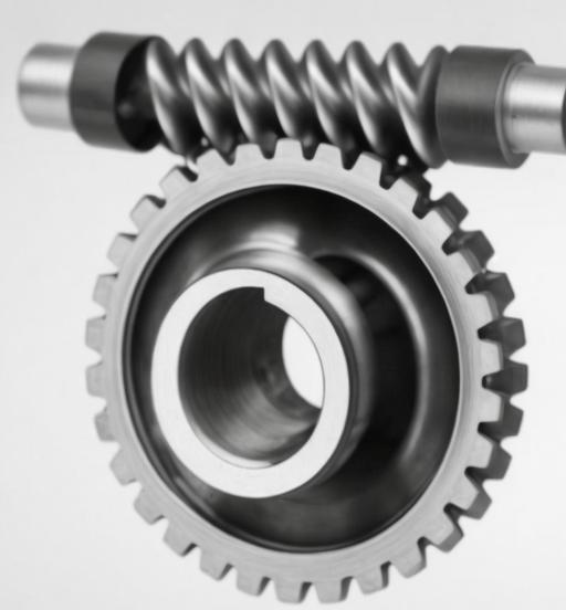
Industrial robots have revolutionized manufacturing by enabling automated, precise, and efficient production processes. At the core of these robots are precision reducers, which play a pivotal role in motion transmission. Among various types, worm gear reducers offer unique advantages such as compact structure, large transmission ratio, and smooth operation, making them suitable for robotic joints requiring high torque and precision. However, traditional worm gear reducers suffer from issues like low transmission efficiency, significant wear, and limited load capacity due to single-worm drive structures. To address these, I propose a three-worm driven worm gear reducer, leveraging multiple worms to distribute loads, reduce friction, and enhance overall performance.
The research objectives are threefold:
- Develop a mathematical model for a three-worm driven worm gear mechanism.
- Design and validate the structural parameters of the reducer through finite element analysis (FEA) and kinematic simulations.
- Fabricate a prototype and test its performance in terms of transmission accuracy, backlash, and efficiency.
2. Mathematical Modeling of the Three-Worm Driven Worm Gear Mechanism
2.1 Transmission Principle
The three-worm driven worm gear mechanism features three worms symmetrically positioned around a single worm gear, each driven by a separate shaft. This configuration ensures uniform load distribution, reduces relative sliding velocity between worms and the worm gear,and minimizes meshing backlash. The worms rotate in the same direction, driving the worm gear to rotate in a perpendicular plane, as shown in the kinematic diagram.
2.2 Coordinate System Setup
To model the mechanism, I established static and dynamic coordinate systems for both worms and the worm gear. Let \(\sum_{i}(O_{i}; i_{i}, j_{i}, k_{i})\) represent the static coordinate system for the i-th worm, and \(\sum_{w}(O_{w}; i_{w}, j_{w}, k_{w})\) for the worm gear. The dynamic coordinate systems \(\sum_{i}’\) and \(\sum_{w}’\) account for rotational motions, with angular velocities \(\omega_{i}\) for worms and \(\omega_{w}\) for the worm gear.
2.3 Vector and Coordinate Transformations
Using spatial geometry, I derived transformation matrices between coordinate systems. For a point P in the worm’s coordinate system, its position in the worm gear’s system is given by:\(\begin{bmatrix} x_{w} \\ y_{w} \\ z_{w} \\ 1 \end{bmatrix} = B_{i-w} \begin{bmatrix} x_{i} \\ y_{i} \\ z_{i} \\ 1 \end{bmatrix}\) where \(B_{i-w}\) is the homogeneous transformation matrix incorporating rotation and translation between systems.
2.4 Meshing Geometry and Equations
The meshing condition between a worm and the worm gear requires that the relative velocity at the contact point is zero. This leads to the meshing equation:\(\mathbf{v}_{w} – \mathbf{v}_{i} – \boldsymbol{\omega}_{w} \times \mathbf{r}_{w} + \boldsymbol{\omega}_{i} \times \mathbf{r}_{i} = \mathbf{0}\) where \(\mathbf{v}_{w}\), \(\mathbf{v}_{i}\) are linear velocities, and \(\mathbf{r}_{w}\), \(\mathbf{r}_{i}\) are position vectors of the contact point in worm gear and worm coordinates, respectively.
The transmission ratio i of the three-worm system is defined as:\(i = \frac{\omega_{i}}{\omega_{w}} = \frac{z_{w}}{z_{i}}\) where \(z_{w}\) is the number of worm gear teeth, and \(z_{i}=1\) for each worm (single-threaded).
3. Structural Design of the Precision Worm Gear Reducer
3.1 Technical Specifications
The reducer is designed to meet industrial robot requirements, summarized in Table 1:
| Parameter | Specification |
|---|---|
| Input speed | 1500 rpm |
| Output torque | 1125 N·m |
| Transmission error | ≤ 50 arcseconds |
| Transmission efficiency | ≥ 70% |
| Backlash | ≤ 60 arcseconds |
| Service life | ≥ 6000 hours |
| Dimensions (L×W×H) | 262×262×100 mm |
| Weight | 18 kg |
3.2 Gear and Worm Gear Parameters
3.2.1 Gear Design
The reducer employs a two-stage gear drive before the worm gear stage. The first stage uses helical gears with parameters:
- Module (m): 1 mm
- Pressure angle (\(\alpha\)): 20°
- Number of teeth (input gear): 30
- Number of teeth (drive gear): 72
- Helix angle (\(\beta\)): 45°
The second stage uses bevel gears with:
- Module (m): 1.5 mm
- Pressure angle (\(\alpha\)): 20°
- Number of teeth: 20 each
3.2.2 Worm Gear Parameters
The three-worm driven worm gear system features:
- Worm material: 40Cr (quenched, HRC 48-55) – worm gear material: ZCuSn10P1 (high-strength bronze)
- Module (m): 1.5 mm
- Number of worm gear teeth (\(z_{w}\)): 45
- Worm diameter coefficient (q): 12.1
- Center distance (a): 43.875 mm
Key geometric dimensions are calculated as:
- Worm pitch diameter: \(d_{1} = mq = 18.15\) mm – worm gear pitch diameter: \(d_{w} = mz_{w} = 67.5\) mm
- Worm lead angle: \(\lambda = \arctan(z_{i}/q) = \arctan(1/12.1) \approx 4.76°\)
3.3 Bearing and Support Frame Design
Tapered roller bearings (SKF 61801, 61906, 61802) are selected for high radial and axial load capacity. The support frame, made of GCr15 alloy, is designed to withstand reaction forces from the transmission system, with a focus on high torsional stiffness and low weight.
4. Finite Element Analysis (FEA)
4.1 Gear and Worm Gear Stress Analysis
Using ANSYS Workbench, I performed static and transient stress analysis on the gear train and worm gear components. The contact stress \(\sigma_{H}\) in gear meshing is calculated by the Hertzian contact theory:\(\sigma_{H} = \sqrt{\frac{F_{t} u}{b \pi} \cdot \frac{2 E}{u^{2} – 1}}\) where \(F_{t}\) is the tangential force, b is the face width, u is the gear ratio, and E is the equivalent elastic modulus.
For the worm gear pair, the bending stress \(\sigma_{F}\) on the worm gear teeth is given by:\(\sigma_{F} = \frac{K T_{2}}{m^{2} d_{1} z_{w}} Y_{F}\) where K is the load factor, \(T_{2}\) is the output torque, and \(Y_{F}\) is the form factor.
4.2 Modal Analysis
Modal analysis was conducted to determine the natural frequencies and vibration modes of the reducer. The first six natural frequencies are listed in Table 2, showing that the lowest natural frequency (4165.3 Hz) is far above the expected excitation frequencies (50 Hz input rotation frequency, 2570 Hz meshing frequency), ensuring no resonance occurs.
| Mode | Natural Frequency (Hz) | Deformation Mode |
|---|---|---|
| 1 | 4165.3 | Worm gear shaft vertical vibration |
| 2 | 4174.4 | Worm gear shaft lateral vibration |
| 3 | 4179.8 | Worm gear shaft lateral vibration |
| 4 | 4469.1 | Worm gear shaft vertical vibration |
| 5 | 4476.7 | Worm gear shaft tangential vibration |
| 6 | 4481 | Gear shaft torsional vibration |
5. Kinematic Simulation with ADAMS
5.1 Virtual Prototype Setup
The 3D model of the reducer, created in SolidWorks, was imported into ADAMS for kinematic simulation. Key components (gears, worms, worm gear,shafts) were assigned material properties (density, elastic modulus, Poisson’s ratio), and contact pairs were defined with a friction coefficient of 0.15.
5.2 Simulation Results
The input shaft was driven at 1404 rpm, and the output speed was measured. Table 3 compares theoretical and simulated speeds for each stage:
| Component | Theoretical Speed (rpm) | Simulated Speed (rpm) | Relative Error |
|---|---|---|---|
| Input gear | 1404 | 1404 | 0% |
| Drive gear | 585 | 584.36 | 0.11% |
| Worm | 585 | 583.59 | 0.24% |
| worm gear (Output) | 13 | 12.92 | 0.59% |
The transmission error, defined as the difference between the theoretical and actual output angles, was calculated using:\(\text{Transmission Error} = \theta_{\text{theo}} – \theta_{\text{actual}}\) Figure 1 shows the angular velocity curves for each stage, confirming smooth transmission with minimal error.
5.3 Load Sharing Analysis
The load sharing coefficient \(B_{sp}\), measuring the uniformity of load distribution among the three worms, was analyzed for different center distances and input speeds. As the center distance decreased (Table 4), \(B_{sp}\) approached 1, indicating better load balance. Similarly, increasing input speed beyond 1400 rpm stabilized the load sharing (Table 5).
| Center Distance (mm) | Load Sharing Coefficient |
|---|---|
| 41 | 1.016 |
| 42 | 1.021 |
| 43 | 1.023 |
| 44 | 1.023 |
| 45 | 1.027 |
| 46 | 1.030 |
| Input Speed (rpm) | Load Sharing Coefficient |
|---|---|
| 1300 | 1.051 |
| 1400 | 1.027 |
| 1500 | 1.021 |
| 1600 | 1.021 |
| 1700 | 1.021 |
| 1800 | 1.020 |
6. Prototype Fabrication and Testing
6.1 Manufacturing Process
The prototype was fabricated using CNC machining for precision components (worms, worm gear,gears) and heat treatment to enhance durability. Key manufacturing steps included:
- Cutting raw materials (40Cr for worms/gears, ZCuSn10P1 for worm gear).
- CNC turning and milling for geometric precision.
- Heat treatment (quenching and tempering) for hardness and wear resistance.
- Surface grinding for smooth meshing surfaces.
6.2 Performance Testing
The prototype was tested on a custom-built test bench to measure transmission accuracy, backlash, and efficiency.
6.2.1 Transmission Accuracy
Using direct measurement with optical encoders, the maximum transmission error was found to be 40.13 arcseconds, within the design limit of 50 arcseconds. The error spectrum (Figure 2) showed dominant frequencies at 10 Hz and 702 Hz, corresponding to worm and gear meshing frequencies.
6.2.2 Backlash
Backlash was measured by reversing the input direction and recording the output delay. The static backlash was 0.47 arcminutes, well below the allowable 60 arcseconds, indicating minimal play in the three-worm drive system.
6.2.3 Transmission Efficiency
Efficiency was calculated as:\(\eta = \frac{T_{output}}{T_{input} \cdot i} \times 100\%\) Test results (Table 6) showed efficiency increasing with load, reaching 80.65% at rated torque (600 N·m), slightly lower than the target but within acceptable industrial standards.
| Input Speed (rpm) | Input Torque (N·m) | Output Torque (N·m) | Efficiency (%) |
|---|---|---|---|
| 200 | 24 | 120 | 53.12 |
| 200 | 48 | 240 | 73.34 |
| 200 | 72 | 360 | 75.23 |
| 200 | 96 | 480 | 78.21 |
| 200 | 120 | 600 | 80.65 |
7. Discussion
The three-worm driven worm gear reducer demonstrates superior load distribution and reduced backlash compared to traditional single-worm designs. The mathematical model accurately predicts meshing behavior, while FEA confirms structural integrity under load. Kinematic simulations validate the transmission principle, and prototype testing shows promising performance in precision and durability.
However, challenges remain, such as improving transmission efficiency further by optimizing lubrication and reducing sliding friction, as well as enhancing manufacturing processes to maintain precision over long periods. Future work will focus on integrating advanced materials and refining the worm profile to minimize wear and boost efficiency.
8. Conclusion
In this research, I have designed, simulated, and tested a precision worm gear reducer for industrial robots, leveraging a three-worm drive mechanism to address limitations of conventional reducers. Key achievements include:
- A robust mathematical model for three-worm driven worm gear systems, enabling precise parameter design.
- Structural optimization through FEA, ensuring high load capacity and resistance to resonance.
- A functional prototype with measured transmission error of 40.13 arcseconds, backlash of 0.47 arcminutes, and efficiency up to 80.65%, meeting critical industrial specifications.