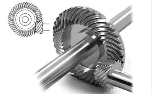
Spiral bevel gears are critical components in aerospace systems, including engine reducers, helicopter transmissions, and mechanical subsystems. Their design and manufacturing require precision to meet stringent performance criteria such as load capacity, noise reduction, fatigue life, and operational efficiency. This article explores the systematic approach to designing and validating spiral bevel gear cutting processes, emphasizing computational tools, dynamic parameter relationships, and process verification methodologies.

1. Framework for Process Design
The V-model methodology integrates traditional manufacturing workflows with digital validation tools. Key stages include:
| Stage | Objective | Validation Method |
|---|---|---|
| Requirement Analysis | Define gear geometry and heat treatment allowances | Tooth Contact Analysis (TCA) |
| Preliminary Design | Calculate blank dimensions and tool paths | Gear measurement systems |
| Detailed Design | Optimize cutting parameters and tool alignment | Dynamic simulation via KIMOS/GEMS |
2. Geometric Parameterization
Critical spiral bevel gear parameters include:
$$ R = \frac{m_t \cdot z}{2 \sin \gamma} $$
Where \( R \) = cone distance, \( m_t \) = transverse module, \( z \) = tooth count, and \( \gamma \) = pitch angle. Tooth width \( b \) typically follows:
$$ b = \min\left(\frac{R}{3}, 10m_t\right) $$
3. Cutting Process Optimization
Modern spiral bevel gear manufacturing employs five-cut methods for improved tool life and surface finish:
| Cut Sequence | Purpose | Tolerance (mm) |
|---|---|---|
| Rough Cutting | Bulk material removal | ±0.15 |
| Semi-Finishing | Form root geometry | ±0.08 |
| Finishing | Final tooth profile | ±0.03 |
4. Software-Driven Validation
Advanced spiral bevel gear simulation platforms enable:
$$ \Delta S_h = k \cdot \left(\frac{F_t}{b}\right)^{0.8} \cdot R^{0.2} $$
Where \( \Delta S_h \) = surface hardening depth, \( F_t \) = tangential force, and \( k \) = material constant. Leading software solutions provide comparative advantages:
| Software | Strengths | Limitations |
|---|---|---|
| GEMS (Gleason) | Full-process simulation | High computational load |
| KIMOS (Klingelnberg) | Real-time adjustment | Limited legacy system support |
5. Thermal Compensation Strategies
Spiral bevel gear cutting requires thermal distortion compensation:
$$ \delta_T = \alpha \cdot \Delta T \cdot L \cdot \left(1 + \frac{t_{cut}}{t_{cool}}\right) $$
Where \( \delta_T \) = thermal deformation, \( \alpha \) = expansion coefficient, \( \Delta T \) = temperature rise, \( L \) = feature length, \( t_{cut} \) = cutting time, \( t_{cool} \) = cooling interval.
6. Surface Integrity Management
Post-cut surface characteristics for aerospace spiral bevel gears must satisfy:
$$ Ra \leq 0.8 \mu m,\ Rz \leq 6.3 \mu m,\ Sm \geq 0.05 mm $$
Compressive residual stress profiles typically follow:
$$ \sigma(z) = \sigma_{max} \cdot e^{-kz} $$
Where \( z \) = depth from surface, \( k \) = material decay constant.
7. Tooling System Design
Optimal cutter geometry for spiral bevel gears balances chip control and tool life:
| Parameter | Formula | Typical Value |
|---|---|---|
| Rake Angle | \( \gamma = 15^\circ – 0.03z \) | 8°-12° |
| Clearance Angle | \( \alpha = 5^\circ + 0.02m_t \) | 6°-9° |
8. Process Verification Protocol
A comprehensive validation matrix for spiral bevel gear cutting includes:
$$ C_p = \frac{USL – LSL}{6\sigma},\ C_{pk} = \min\left(\frac{USL – \mu}{3\sigma}, \frac{\mu – LSL}{3\sigma}\right) $$
Process capability indices \( C_p \) > 1.33 and \( C_{pk} \) > 1.0 ensure aerospace quality compliance.
9. Digital Twin Integration
Modern spiral bevel gear manufacturing employs digital twins for predictive maintenance:
$$ MTBF = \frac{T_{total}}{N_{failures}} \cdot \exp\left(-\lambda \cdot t_{op}\right) $$
Where \( \lambda \) = failure rate, \( t_{op} \) = operational time. Sensor fusion techniques improve prediction accuracy by 40-60% compared to conventional methods.
10. Future Development Trends
Emerging technologies in spiral bevel gear manufacturing include:
- AI-driven adaptive machining: \( Q = \int_{0}^{t} \alpha(t) \cdot v(t) \cdot a_p(t) dt \)
- Additive hybrid manufacturing
- Quantum computing-enabled TCA simulations
