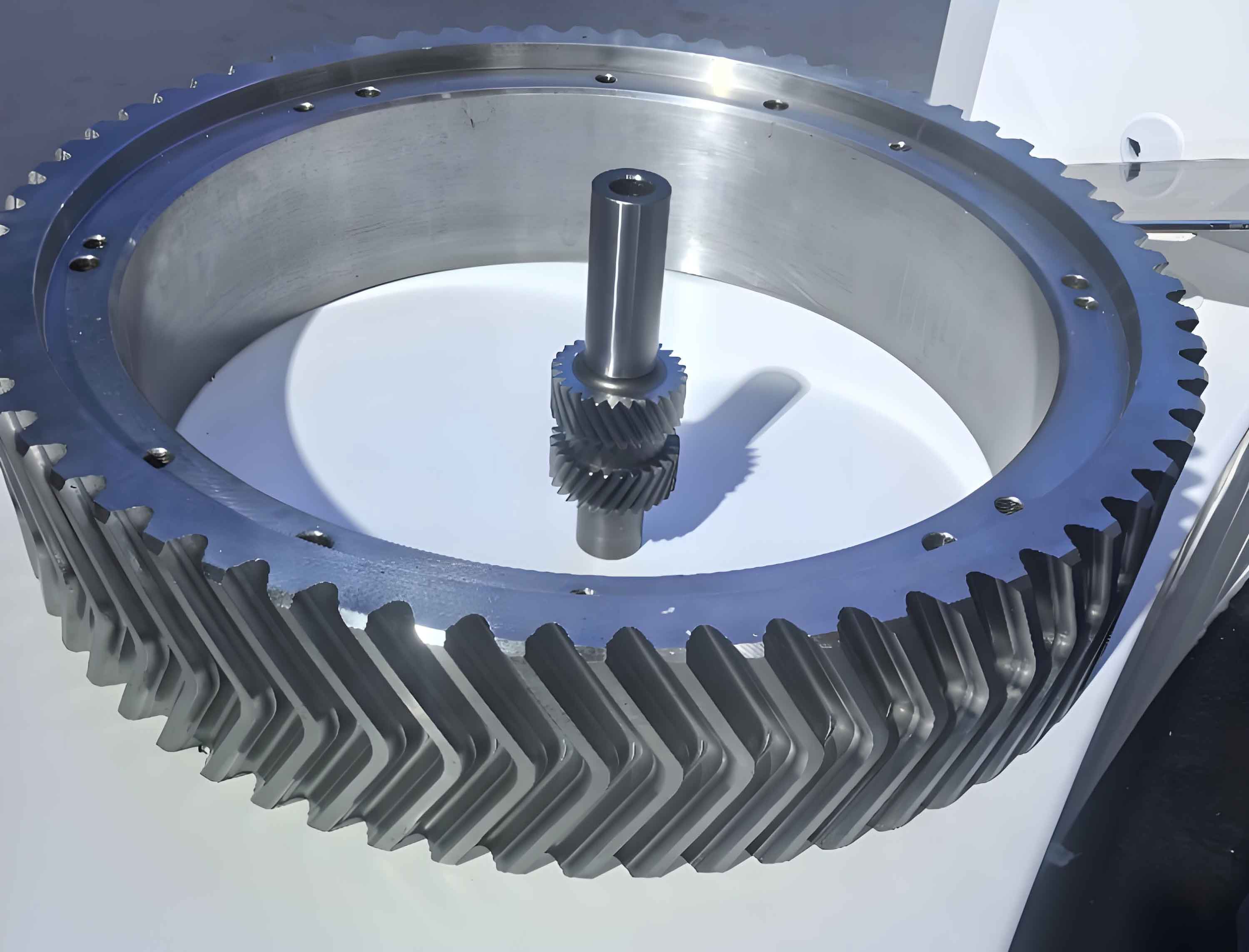
Herringbone gears are widely used in heavy-load applications due to their high load-bearing capacity, elimination of axial forces, and smooth transmission. However, tooth surface twisting—a machining error caused by spiral line modifications during form grinding—significantly impacts gear accuracy and service life. This paper proposes a counter-twist machining method to mitigate principle-based errors in herringbone gear grinding.

1. Contact Line Analysis in Form Grinding
1.1 Coordinate System for Spatial Meshing
The spatial relationship between the grinding wheel and herringbone gear is defined using coordinate systems. Let $O_s – x_s y_s z_s$ represent the grinding wheel frame and $O_f – x_f y_f z_f$ the gear frame. The transformation matrix between these systems is expressed as:
$$
\mathbf{M}_\theta = \begin{bmatrix}
\cos\theta & \sin\theta & 0 & 0 \\
-\sin\theta & \cos\theta & 0 & 0 \\
0 & 0 & 1 & -p\theta \\
0 & 0 & 0 & 1
\end{bmatrix}, \quad
\mathbf{M}_\beta = \begin{bmatrix}
-1 & 0 & 0 & a – \Delta a \\
0 & -\cos\beta & -\sin\beta & 0 \\
0 & -\sin\beta & \cos\beta & 0 \\
0 & 0 & 0 & 1
\end{bmatrix}
$$
where $p$ is the helical parameter, $\theta$ the rotation angle, $\beta$ the wheel installation angle, and $\Delta a$ the radial feed adjustment.
1.2 Contact Line Derivation
The contact line equation for a point $G(x_0, y_0, z_0)$ on the tooth surface is derived from the meshing condition:
$$
z_0 J_x + a J_y \cot\Sigma + (a – x_0 + p \cot\Sigma) J_z = 0
$$
where $(J_x, J_y, J_z)$ denotes the normal vector at the contact point, and $\Sigma$ represents the crossed-axis angle.
2. Tooth Surface Twisting and Counter-Twist Models
2.1 Mechanism of Tooth Surface Twisting
Spiral line crowning during form grinding creates non-uniform material removal. The maximum radial feed occurs at the gear’s entry/exit positions, causing asymmetric cutting depths. This generates tooth surface twisting quantified by:
$$
T’ = \Delta_1 – f(z) + \frac{Q}{\phi}
$$
where $\Delta_1$ is the maximum crowning modification, $f(z)$ the spiral line profile function, and $Q/\phi$ the normal curvature contribution.
2.2 Counter-Twist Model
The counter-twist model reverses the meshing direction to offset twisting errors. The modified transformation matrix becomes:
$$
\mathbf{M}’_\beta = \begin{bmatrix}
-1 & 0 & 0 & a \\
0 & -\cos\beta & -\sin\beta & \Delta s \\
0 & -\sin\beta & \cos\beta & 0 \\
0 & 0 & 0 & 1
\end{bmatrix}
$$
The net machining error after counter-twist compensation is:
$$
\zeta = T” \cos\gamma – T’ \cos\gamma
$$
where $T”$ represents the counter-twist deformation.
3. Optimization and Verification
3.1 Monte Carlo Parameter Optimization
Key parameters for herringbone gear modification are optimized using Monte Carlo simulations. The optimization ranges are:
| Parameter | Range |
|---|---|
| Crowning Modification | 2–40 μm |
| Spiral Line Slope | -4°–16° |
The probability density function for parameter selection follows:
$$
h(x) = \frac{1}{\sigma\sqrt{2\pi}} e^{-\frac{(x-\mu)^2}{2\sigma^2}}
$$
3.2 Finite Element Analysis
Transmission error (TE) and contact stress are compared for three cases: unmodified, twisted, and counter-twisted herringbone gears. The TE peak-to-peak values show:
| Case | TE Reduction |
|---|---|
| Twisted Surface | 22.2% vs. Unmodified |
| Counter-Twisted Surface | 71.95% vs. Twisted |
The contact stress distribution demonstrates that counter-twisting achieves 39.3% lower maximum stress compared to conventional twisted surfaces under heavy loads.
4. Conclusion
1) The counter-twist machining method effectively reduces principle-based errors in herringbone gear form grinding, decreasing maximum twisting deformation by 57.25%.
2) Monte Carlo optimization identifies optimal crowning parameters (1.6 μm modification with 2° spiral slope), balancing transmission accuracy and load capacity.
3) Finite element results validate that counter-twisted herringbone gears exhibit 71.95% lower transmission error and more uniform contact patterns compared to traditional twisted surfaces.
This methodology provides a systematic approach for precision manufacturing of high-performance herringbone gears in industrial applications.
