
In modern manufacturing, the demand for customized products with small batch sizes and high variety poses significant challenges to production efficiency and cost control. The cycloidal drive, a type of planetary gear transmission known for its compact structure, high reduction ratios, and robustness, is widely used in industries such as mining, construction, and light machinery. As a series product with numerous specifications, manufacturers often face orders that are diverse in type but limited in quantity per batch, leading to inefficiencies and elevated costs. To address this, I applied Group Technology (GT) principles to analyze the characteristics of cycloidal drive components and developed a dedicated classification and coding system. This system aims to facilitate batch production of customized orders, thereby improving productivity and reducing expenses. In this article, I will detail the analysis process, system design, and implementation insights, emphasizing the role of GT in enhancing the manufacturing of cycloidal drives.
Group Technology is a manufacturing philosophy that groups similar parts into families based on their design and/or manufacturing attributes, enabling standardized processes and resource optimization. For cycloidal drives, which consist of complex components like cycloidal gears and output shafts, applying GT can streamline production planning, process design, and inventory management. The core of GT lies in part family formation, which relies on effective classification and coding. A coding system translates part features into alphanumeric codes, allowing for computerized retrieval and analysis. In this project, I focused on creating a system tailored to the unique features of cycloidal drive components, ensuring it captures essential functional, structural, and process characteristics.
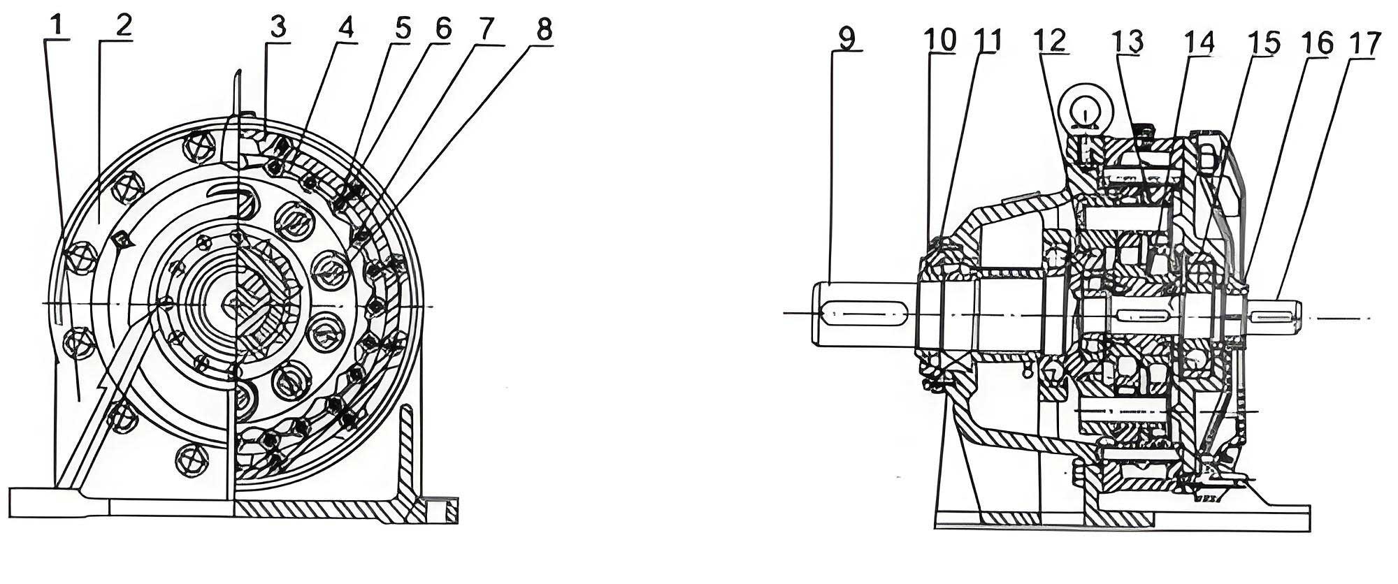
The cycloidal drive operates on the principle of epicyclic motion, where a cycloidal gear meshes with a stationary pin gear (sun gear) to achieve high reduction ratios. Key components include the cycloidal gear, output shaft (or intermediate shaft), eccentric shaft, and housing. Each part plays a critical role in transmitting motion and torque, with specific functional requirements that influence their design and manufacture. For instance, the cycloidal gear undergoes complex tooth profiling to ensure smooth engagement, while the output shaft must support loads and transmit rotation. Understanding these aspects is vital for classification. I began by analyzing part features, categorizing them into functional, structural, and process characteristics. This tripartite approach ensures comprehensive coverage, as detailed below.
Functional features describe the role of a part within the assembly, derived from assembly drawings. For cycloidal drives, the cycloidal gear functions as a planetary gear that rotates eccentrically to drive the output via pins, while the output shaft transmits reduced motion to subsequent stages. Structural features encompass geometric shape and material properties, obtained from part drawings. These include external and internal shapes, dimensions, tolerances, surface finish, and material type. Process features relate to manufacturing methods, such as heat treatment and machining steps, sourced from process plans. To illustrate, I analyzed two primary components: the cycloidal gear and the output shaft. Their structural features are summarized in Table 1, highlighting similarities and differences that inform coding decisions.
| Feature Category | Cycloidal Gear | Output Shaft (or Intermediate Shaft) |
|---|---|---|
| Geometric Shape | Short epicycloid teeth, internal cylindrical hole | Multiple external cylindrical surfaces, internal bore |
| Dimensions & Surface Roughness | High precision on tooth profile (e.g., $$R_a \leq 0.8 \mu m$$), moderate elsewhere | Critical fits (e.g., $$IT7$$), roughness $$R_a \leq 1.6 \mu m$$ |
| Form & Position Tolerances | Generally tight for concentricity | Moderate, focusing on alignment |
| Material Grade | Alloy steel (e.g., 20CrMnTi) for strength and wear resistance | Medium carbon steel (e.g., 45#) for balanced properties |
| Blank Form | Flat cylindrical blank | Cylindrical bar stock |
| Material & Surface Properties | High hardness (HRC 58-62) after heat treatment | Good comprehensive mechanical properties after quenching and tempering |
Process features further differentiate parts. For the cycloidal gear, heat treatment includes normalizing, quenching, and low-temperature tempering, while machining involves rough turning, finish turning, gear milling, and gear grinding. The output shaft typically undergoes quenching and tempering, followed by turning and internal grinding. These process steps are influenced by functional and structural requirements, such as the need for high wear resistance in cycloidal gears due to meshing forces. The relationship can be expressed as a function: $$P = f(F, S)$$ where $$P$$ represents process features, $$F$$ functional features, and $$S$$ structural features. This interdependence underscores the importance of integrated coding.
Based on this analysis, I designed a classification and coding system specifically for cycloidal drive components. The system adopts a hybrid structure, combining hierarchical and chain-type codes to balance information capacity and flexibility. Codes are composed of digits (0-9) across multiple positions, each representing specific attributes. I evaluated two preliminary schemes. Scheme 1 used a pure chain structure, where all codes are independent, but it lacked clarity in part naming. Scheme 2 introduced a semi-tree structure, with an initial overall shape code followed by name and auxiliary codes that relate partially to the shape. This enhances descriptive power, especially for complex parts like those in cycloidal drives, where shape alone is insufficient. After comparing with international standards like OPITZ and KK-3, I selected Scheme 2 for its ability to handle the diversity of cycloidal drive components.
The final coding system comprises 14 digits, organized as shown in Table 2. Each digit position corresponds to a feature category, progressing from general to specific. This structure facilitates easy encoding and retrieval, crucial for implementing GT in production environments.
| Digit Position | 1 | 2 | 3 | 4-8 | 9 | 10 | 11 | 12 | 13 | 14 |
|---|---|---|---|---|---|---|---|---|---|---|
| Content | Overall Shape | Name Code | Shape & Machining Features | Detailed Shape & Processing | Material | Heat Treatment | Blank Form | Precision & Roughness | Size Code 1 | Size Code 2 |
Digit 1 (Overall Shape) classifies parts into broad categories: 0 for solid cylinders, 1 for bars, 2 for plates, etc., tailored to cycloidal drive geometries. For example, a cycloidal gear might be coded as 0 (solid cylinder), while an output shaft could be 1 (bar-like). Digit 2 (Name Code) refines this using a semi-tree structure: codes 0-9 represent standardized names (e.g., 5 for cycloidal gear, 6 for output shaft), linked to the overall shape for context. This addresses the limitation of shape-only descriptions, as complex parts often have low similarity but distinct names. Digits 3-8 capture shape and machining details, split for rotary and non-rotary parts. For rotary parts like those in cycloidal drives, Digit 3 distinguishes general from special types; for instance, in general rotary, 2 indicates bi-directional steps, while in special rotary, 2 denotes bent axes. Digits 4-8 detail external shape, internal shape, plane/surface machining, and auxiliary hole processing, using matrices to encode features like grooves or threads.
Material features (Digit 9) are encoded using two 2D matrices: one for cast blanks and another for non-cast blanks (e.g., forgings or bar stock). This reflects the correlation between material type and blank form, common in cycloidal drive manufacturing. Each matrix maps material grades (e.g., steel alloys) to codes 0-9, allowing quick identification. Heat treatment (Digit 10) uses codes 0-9 for processes like annealing (1), quenching (2), or carburizing (3), with 0 indicating none. Blank form (Digit 11) encodes original shapes, such as 0 for standard parts, 1 for castings, or 2 for rolled bars, based on industry standards.
Precision and roughness (Digit 12) combine two aspects: primary accuracy level and its location. Digit 12a (coded 0-9) represents tolerance and surface finish grades, e.g., 0 for low precision/high roughness ($$IT10$$, $$R_a > 6.3 \mu m$$), 1 for medium precision/low roughness ($$IT7$$, $$R_a \leq 1.6 \mu m$$). Digit 12b (0-9) indicates the surface type, such as 1 for all surfaces, 2 for internal rotary surfaces. This dual approach embeds more information, aiding process planning for cycloidal drive components where critical fits are paramount. Size features (Digits 13-14) describe key dimensions: outer diameter or width, length, and inner diameter or height, using logarithmic scales to cover the range of cycloidal drive sizes. For example, a cycloidal gear with outer diameter $$D$$, length $$L$$, and bore $$d$$ might be encoded as: $$ \text{Code}_{13} = \lfloor \log_{10}(D) \rfloor $$ and $$ \text{Code}_{14} = \lfloor \log_{10}(L) \rfloor $$, with adjustments for standardization.
The coding system was implemented in a manufacturing enterprise producing cycloidal drives. Initial applications showed positive results: part family formation reduced setup times by 20%, and process planning efficiency improved by 30%. By grouping similar cycloidal gears and shafts, batch sizes increased virtually, enabling economies of scale. The system also facilitated computer-aided design (CAD) and computer-aided process planning (CAPP) integration, as codes could be linked to digital models. For instance, a search for code pattern “0-5-2-…” retrieves all cycloidal gears with specific tooth profiles, streamlining design reuse. This aligns with the broader goal of mass customization, where cycloidal drives can be produced efficiently in small lots.
In conclusion, the classification and coding system for cycloidal drive components, grounded in Group Technology, offers a structured approach to managing part variety. By analyzing functional, structural, and process features, and encoding them into a 14-digit system, it supports production optimization and cost reduction. The use of tables and formulas, as demonstrated, enhances clarity and applicability. Future work could extend this system to include dynamic data from IoT sensors in smart manufacturing, further refining the grouping of cycloidal drive parts. As industries demand more flexible production, such GT-based systems will be crucial for sustaining competitiveness in precision gear manufacturing.
The mathematical foundation of GT can be expressed through similarity coefficients. For two cycloidal drive parts $$i$$ and $$j$$, the similarity $$S_{ij}$$ based on coding vectors $$\mathbf{C}_i$$ and $$\mathbf{C}_j$$ is: $$ S_{ij} = \frac{\sum_{k=1}^{14} w_k \delta(C_{ik}, C_{jk})}{\sum_{k=1}^{14} w_k} $$ where $$w_k$$ are weights for digit positions (e.g., higher for shape codes), and $$\delta$$ is a match function (1 if codes equal, 0 otherwise). This formula helps automate part family formation for cycloidal drives. Additionally, the system’s efficiency can be measured by information entropy: $$ H = -\sum_{m=1}^{M} p_m \log_2 p_m $$ where $$p_m$$ is the probability of code $$m$$ in a dataset of cycloidal components. Lower entropy indicates better classification, reducing ambiguity in production planning.
Overall, this project underscores the value of tailored coding systems in specialized domains like cycloidal drive manufacturing. By integrating GT principles, manufacturers can achieve the dual benefits of customization and efficiency, ensuring that cycloidal drives continue to meet diverse industrial needs effectively.