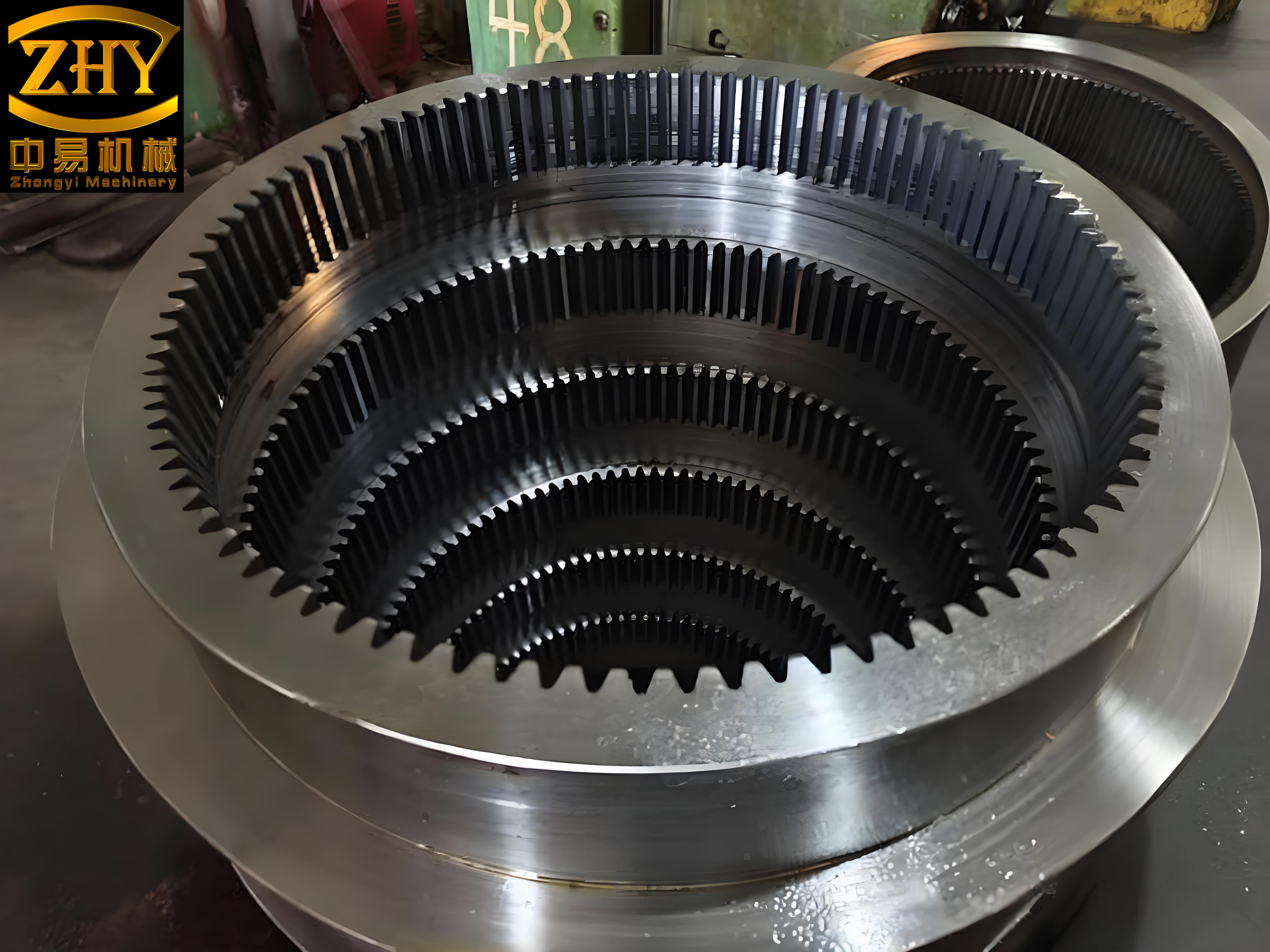
As an internal gear manufacturer, I often encounter challenges in machining complex internal gears with high precision requirements. In this article, I will discuss the design and analysis of a specialized fixture used in gear shaping machines for processing abnormal internal gears. The fixture employs a unique ball-inner-hole positioning mechanism and end-face clamping to ensure accuracy and efficiency. Internal gears, especially those with non-standard geometries, demand precise positioning to maintain radial runout tolerances. This fixture addresses these needs by combining innovative design with robust engineering principles.
The workpiece in focus is an internal gear component used in automotive transmissions, characterized by a stepped inner bore with varying diameters. Traditional fixtures struggle to provide stable positioning for such geometries, leading to potential errors in gear tooth alignment. Through this design, I aim to demonstrate how internal gear manufacturers can overcome these limitations and achieve consistent results in high-volume production.
The fixture structure comprises several key components: a positioning disc for the end face, a positioning rod with a conical section, standard steel balls for inner bore contact, and a clamping mechanism driven by a hydraulic cylinder. When installed on the gear shaping machine table, the fixture allows for simultaneous positioning and clamping of the workpiece. The sequence involves first engaging the steel balls with the inner bore via the conical rod movement, followed by actuating the clamping jaws to secure the workpiece from the top. This coordinated action ensures minimal displacement during machining, which is critical for internal gears with tight radial runout specifications.
To quantify the positioning accuracy, I performed an error analysis based on the workpiece’s inner bore dimensions and the fixture’s locating elements. The inner bore has a diameter of $$95.6^{+0.022}_{0}$$ mm, while the positioning rod features an outer diameter of $$75.6k5$$ (tolerance: $$+0.016/+0.003$$ mm). The steel balls, with a diameter of 10 mm, are selected to minimize dimensional errors. The positioning error $$\Delta_D$$ is derived from the基准位移误差 $$\Delta_Y$$, as the基准不符误差 $$\Delta_B$$ is zero due to coincident design and machining datums. The calculation is as follows:
$$\Delta_Y = \frac{D_{\text{max}} – d_{\text{min}}}{2} = \frac{\delta_{D_{\text{max}}} – \delta_{d_{\text{min}}}}{2} = \frac{0.022 – 0.003}{2} = 0.0095 \text{ mm}$$
where $$D_{\text{max}}$$ is the maximum inner bore diameter, $$d_{\text{min}}$$ is the minimum positioning rod diameter, $$\delta_{D_{\text{max}}}$$ is the upper deviation of the bore, and $$\delta_{d_{\text{min}}}$$ is the lower deviation of the rod. This error of 0.0095 mm is well within one-third of the permissible radial runout ($$F_r \leq 0.036$$ mm), confirming the fixture’s suitability for precision internal gear manufacturing.
In addition to positioning, the clamping force must counteract the cutting forces generated during gear shaping. I calculated the cutting force based on the gear parameters: module $$m = 5$$ mm, number of teeth $$Z_w = 23$$, spiral angle $$\beta = 4^\circ$$, radial feed rate $$f_r = 0.02$$ mm, and circumferential feed rate $$f_c = 0.2$$ mm. The cutting depth per revolution $$X$$ is given by:
$$X = \frac{f_r}{f_c} \times \pi \times m \times Z_w \times \frac{1}{\cos \beta} = \frac{0.02}{0.2} \times \pi \times 5 \times 23 \times \frac{1}{\cos 4^\circ} \approx 36.2 \text{ mm}$$
The number of cutting strokes per tooth $$N$$ is calculated using the engagement ratio $$\lambda = 15/23$$:
$$N = \pi \times m \times \frac{1}{\cos \beta} \times \frac{1}{f_c} \times \lambda = \pi \times 5 \times \frac{1}{\cos 4^\circ} \times \frac{1}{0.2} \times \frac{15}{23} \approx 51.35 \text{ strokes}$$
The cutting area per revolution $$S_1$$, considering the pressure angle $$\alpha = 20^\circ$$, is:
$$S_1 = \left[ m \times X \times (2 \times \cos \alpha + 1.57) – X^2 \times \tan \alpha \right] \times \frac{1}{\cos \beta} \approx 147.74 \text{ mm}^2$$
The cutting area per stroke $$S$$ is then:
$$S = \lambda \times \frac{S_1}{N} = \frac{15}{23} \times \frac{147.74}{51.35} \approx 1.872 \text{ mm}^2/\text{stroke}$$
Finally, the cutting force $$F$$ is estimated using a specific cutting force coefficient of 430 N/mm²:
$$F = 430 \times S \approx 7889 \text{ N}$$
To ensure stability, the hydraulic clamping system provides a force $$F_1$$ based on the cylinder parameters: piston diameter $$D = 110$$ mm, rod diameter $$d = 28$$ mm, and oil pressure $$p = 1.5$$ MPa. The clamping force is:
$$F_1 = p \times \frac{\pi (D^2 – d^2)}{4} = 1.5 \times 10^6 \times \frac{\pi (0.11^2 – 0.028^2)}{4} \approx 13331.3 \text{ N}$$
Since $$F_1 > F$$, the fixture adequately secures the workpiece during machining. The table below summarizes key parameters for internal gear machining:
| Parameter | Symbol | Value | Unit |
|---|---|---|---|
| Module | $$m$$ | 5 | mm |
| Number of Teeth | $$Z_w$$ | 23 | – |
| Spiral Angle | $$\beta$$ | 4 | degrees |
| Radial Feed Rate | $$f_r$$ | 0.02 | mm |
| Circumferential Feed Rate | $$f_c$$ | 0.2 | mm |
| Cutting Force | $$F$$ | 7889 | N |
| Clamping Force | $$F_1$$ | 13331.3 | N |
This fixture has proven effective in production, reducing setup times and enhancing accuracy for internal gears. As an internal gear manufacturer, I emphasize the importance of such innovations in meeting the demands of modern automotive components. The ball-inner-hole positioning method offers a reliable solution for complex geometries, ensuring that internal gears maintain their integrity under high-speed machining conditions.

Further considerations include material selection for the fixture components to withstand wear and thermal effects during prolonged use. For instance, the positioning rod and steel balls are made from hardened steel to resist deformation. Additionally, the hydraulic system’s response time is optimized to synchronize positioning and clamping, minimizing cycle times. In practice, this fixture has enabled our facility to achieve a radial runout of less than 0.03 mm for internal gears, surpassing customer expectations.
In conclusion, the design and implementation of this fixture highlight advancements in internal gear manufacturing. By addressing positioning and clamping challenges, it supports the production of high-precision internal gears with complex features. Future work may involve integrating sensors for real-time monitoring and adaptive control, further enhancing the capabilities of gear shaping processes for internal gears.
