
Herringbone gears are widely employed in high power transmission systems such as marine propulsion, helicopter main gearboxes, and turbofan engines due to their high load capacity, excellent smoothness, and elimination of axial thrust. However, misalignments caused by manufacturing errors, assembly errors, thermal deformations, and elastic deflections of shafts and bearings often lead to edge contact, stress concentration, and increased vibration and noise. Gear profile modification and flank line modification are effective means to mitigate these issues. Traditional modification design relies heavily on empirical formulas, trial-and-error rolling inspections, and repeated adjustments, which are time-consuming and costly. The KISSsoft software provides a powerful platform for analytical design and optimization of gear modifications. In this work, I present a systematic approach based on KISSsoft for designing profile and lead modifications of herringbone gears, using transmission error, normal line load, and tooth surface load distribution as evaluation criteria. A case study of an industrial herringbone gear pair demonstrates that the optimized modification parameters significantly improve performance compared to the original design.
1. Introduction
The herringbone gear, also known as a double helical gear, is essentially a pair of helical gears with opposite helix angles machined on a common blank, leaving a central gap for cutter runout. This configuration cancels axial thrust and offers high load sharing capability. Despite these advantages, the meshing behavior of herringbone gears is sensitive to installation errors and elastic deformations, which can cause premature failure due to edge loading or excessive contact stress. Gear modification—both profile modification (tip relief, root relief) and lead modification (crowning, taper)—is a proven technique to improve contact patterns, reduce transmission error, and increase load capacity. The goal of profile modification is to avoid impact at the beginning and end of mesh, while lead modification aims to center the contact band and reduce the peak load per unit length.
Traditional modification design follows industry standards and handbooks such as ISO 21771 and AGMA 109.16. The designer calculates modification amounts and start points using empirical formulas, then manufactures the gears and conducts rolling inspections on a test rig. The contact pattern, vibration, and noise are measured, and if unsatisfactory, the modifications are adjusted and the cycle repeats. This process is iterative and heavily dependent on the experience of the engineer. KISSsoft software, developed by KISSsoft AG in Switzerland, integrates international standards and advanced contact analysis algorithms (including tooth contact analysis and loaded tooth contact analysis) to simulate the meshing behavior of modified gears under realistic operating conditions. It allows the designer to quickly evaluate multiple modification schemes and optimize them without physical prototyping. In this paper, I outline the methodology of using KISSsoft for herringbone gear modification design and demonstrate its application through a concrete example.
2. Modification Design Methodology for Herringbone Gears
2.1 Traditional Method
The traditional method begins by calculating modification parameters from design manuals and standards. For example, the profile modification amount and start diameter are often determined based on the maximum elastic deformation of the tooth pair. The lead modification (crowning) is typically chosen as a fraction of the effective face width to compensate for misalignments. After manufacturing the modified gears, they are assembled in a test rig. The contact pattern is inspected using red lead or blue stain, and the transmission error is measured with encoders. Vibration and noise levels are recorded. If the contact pattern shows edge contact or the transmission error is too high, the modifications are adjusted—either by increasing crowning or changing the profile relief—and the test is repeated. This loop continues until satisfactory results are obtained. While this method is reliable, it is expensive and time-consuming, especially for large or custom herringbone gears.
2.2 KISSsoft-Based Method
The KISSsoft method streamlines the design process. The software allows the user to input the gear geometry (module, number of teeth, pressure angle, helix angle, face width, etc.), material properties, lubrication conditions, and operating torque. For herringbone gears, the gear pair is treated as two separate helical gears (left flank and right flank) because the load path is independent on each side due to the central gap. The software calculates the unmodified contact stress and transmission error, then applies profile and lead modifications according to user-defined parameters or automatically using built-in optimization routines. The analysis yields key performance indicators: transmission error curve over one mesh cycle, line load distribution along the face width, tooth root safety factor, and contact safety factor. Based on these results, the designer adjusts the modification parameters (e.g., tip relief amount, crowning amount, start point) and re-runs the analysis. This iterative process can be completed in minutes, avoiding the lengthy and costly hardware iterations. Figure 1 in the original literature shows the traditional process versus the KISSsoft process; here we embed the corresponding conceptual flowchart in text.
2.3 Evaluation Criteria
To judge the quality of a modification scheme, I select four primary criteria: minimum tooth root bending fatigue safety factor (SFmin), minimum tooth surface contact fatigue safety factor (SHmin), transmission error (TE), and tooth surface load distribution. The safety factors are calculated according to ISO 6336. For general reliability, SFmin ≥ 1.25 and SHmin ≥ 1.00 are recommended; for high reliability, SFmin ≥ 1.6 and SHmin ≥ 1.25. Transmission error is defined as the difference between the actual position of the driven gear and its ideal position assuming perfect involute profiles and no deformation. It is widely accepted as the excitation source of gear whine noise. The peak-to-peak transmission error is a key metric. The tooth surface load distribution should be uniform, avoiding high concentration at either end of the face width. A high load distribution factor KHβ indicates poor load sharing.
2.4 Axis Parallelism Deviation and Its Influence
Axis parallelism deviations arise from bearing deflections, shaft bending, and housing deformations. They are divided into two components: deviation in the plane of axes (f∑δ) and deviation in the perpendicular plane (f∑β). These deviations significantly affect the contact pattern. The recommended maximum values are:
$$ f_{\sum\beta} = 0.5 \left(\frac{L}{b}\right) F_\beta $$
$$ f_{\sum\delta} = 2 f_{\sum\beta} $$
where L is the bearing span, b is the face width, and Fβ is the total helix deviation. For herringbone gears, the deviations must be apportioned between the two helical halves. If the single-sided face width is b and the gap width is c, the effective deviations for each half are:
$$ f’_{\sum\beta} = \frac{b}{2b+c} f_{\sum\beta} $$
$$ f’_{\sum\alpha} = \frac{b}{2b+c} f_{\sum\delta} $$
These values are input into KISSsoft to simulate realistic misalignment. The software then shows how the modification can compensate for these deviations.
3. Case Study: Industrial Herringbone Gear Pair
To demonstrate the application of the KISSsoft method, I consider an industrial herringbone gear reducer from a gearbox. The reducer consists of four herringbone gears (z1 → z2 → z3 → z4). The output shaft (z4) transmits 1000 kW at 1020 r/min. The gear pair under study is z3 (pinion) and z4 (wheel). Each herringbone gear has an overall face width of 2×47 mm plus a 20 mm gap. The material is 18CrNiMo7-6, case hardened to 60–62 HRC. Lubrication is jet-fed ISO VG100 oil. Table 1 lists the basic parameters.
| Parameter | z3 | z4 |
|---|---|---|
| Normal module mn (mm) | 3.5 | 3.5 |
| Number of teeth z | 25 | 110 |
| Normal pressure angle αn (°) | 22.5 | 22.5 |
| Helix angle β (°) | 30 | 30 |
| Hand of helix | left-right | right-left |
| Addendum coefficient h*an | 1.2 | 1.2 |
| Clearance coefficient c*n | 0.45 | 0.45 |
| Root fillet radius coefficient ρ*fp | 0.152 | 0.152 |
| Profile shift coefficient x | 0.05 | −0.05 |
| Single side face width b (mm) | 47 | 47 |
| Gap width c (mm) | 20 | 20 |
| Accuracy grade (ISO) | 5 | 5 |
The original modification parameters used in the existing gear pair are given in Table 2. The original design applied the same profile modification amount and crowning to both pinion and gear. However, analysis revealed high transmission error and concentrated load distribution.
| Parameter | z3 | z4 |
|---|---|---|
| Profile modification amount (μm) | 18 | 18 |
| Profile start diameter dca (mm) | 124.360 | 531.650 |
| Crowning amount (μm) | 27.4 | 27.4 |
The operation conditions: input power to each half of the z3-z4 mesh is 250 kW. The bearing span on the z4 shaft is L = 292.2 mm. The total helix deviation Fβ for grade 5 is 11 μm (based on the larger gear). Applying the formulas for axis parallelism deviation:
$$ f_{\sum\beta} = 0.5 \times \frac{292.2}{114} \times 11 = 14.1 \ \mu\text{m} $$
$$ f_{\sum\delta} = 28.2 \ \mu\text{m} $$
For each helical half (single side width 47 mm, gap 20 mm):
$$ f’_{\sum\beta} = \frac{47}{2\times47+20} \times 14.1 = 5.8 \ \mu\text{m} $$
$$ f’_{\sum\alpha} = \frac{47}{114} \times 28.2 = 11.6 \ \mu\text{m} $$
These values were entered into KISSsoft as axis alignment deviations.
Using KISSsoft, I performed a series of analyses by varying the modification parameters. The aim was to reduce transmission error peak-to-peak, reduce the maximum line load, and achieve a more uniform load distribution while maintaining safety factors. After several iterations, the optimized modification parameters shown in Table 3 were obtained. Note that the profile modification is a quadratic curve (second-order parabola) in both the original and optimized cases.
| Parameter | Original (z3L/z4L/z3R/z4R) | Optimized (z3L/z4L/z3R/z4R) |
|---|---|---|
| Profile modification amount (μm) | 18 / 18 / 18 / 18 | 15 / 15 / 15 / 15 |
| Profile start diameter dca (mm) | 124.360 / 531.650 / 124.360 / 531.650 | 126.532 / 534.118 / 126.532 / 534.118 |
| Crowning amount (μm) on pinion | 27.4 / – / 27.4 / – | 20 / – / 20 / – |
| Helix slope modification (μm) on pinion | – / – / – / – | 10 / – / 10 / – |
| Crowning on gear | 27.4 / 27.4 / 27.4 / 27.4 | – / 0 / – / 0 |
In the optimized design, the pinion (z3) receives a combination of crowning (20 μm) and a small taper (10 μm helix slope modification), while the gear (z4) has no lead modification. The profile modification amount was reduced from 18 μm to 15 μm, and the start diameter was shifted to a slightly larger value (later start of relief). This asymmetric modification scheme proved more effective.
4. Results and Discussion
4.1 Safety Factors
The tooth root bending safety factor SF and contact safety factor SH for each helical half (left and right) are compared in Table 4. Both remain well above the recommended high reliability thresholds. The changes are negligible (<1% variation), indicating that the modifications did not compromise strength.
| Parameter | Original (z3L/z4L) | Optimized (z3L/z4L) | Original (z3R/z4R) | Optimized (z3R/z4R) |
|---|---|---|---|---|
| SF (bending) | 4.872 / 3.557 | 4.857 / 3.546 | 4.872 / 3.557 | 4.857 / 3.546 |
| SH (contact) | 2.105 / 2.202 | 2.101 / 2.199 | 2.105 / 2.202 | 2.101 / 2.199 |
| Scuffing safety (integral temp.) | 4.445 | 4.407 | 4.445 | 4.407 |
| Scuffing safety (flash temp.) | 12.651 | 12.652 | 12.651 | 12.652 |
| KHβ | 1.641 | 1.237 | 1.641 | 1.237 |
The load distribution factor KHβ decreased significantly from 1.641 to 1.237 (a reduction of 24.6%), indicating much better load sharing along the face width.
4.2 Transmission Error
Figure 7 in the original paper shows the transmission error curves. The optimized design yields lower peak-to-peak transmission error. Numerically, the left helical half peak-to-peak TE dropped from 1.483 μm to 0.849 μm (42.8% reduction); the right half dropped from 1.492 μm to 0.797 μm (46.6% reduction). Lower transmission error implies lower excitation of gear whine noise and vibration.
4.3 Normal Line Load
The maximum normal line load along the face width was dramatically reduced. For the left half, the maximum decreased from 484.131 N/mm to 329.552 N/mm (31.9% reduction); for the right half, from 482.181 N/mm to 327.709 N/mm (32.0% reduction). This reduction directly lowers the risk of pitting and scuffing.
4.4 Tooth Surface Load Distribution
Figures 9 and 10 in the original paper illustrate the load distribution on the left and right tooth flanks. In the original design, the load was highly concentrated near the center of the face width (peak stress near mid-face). After optimization, the load spreads more evenly across the entire face width, and the peak contact stress is lowered. This is a direct consequence of the combined crowning and helix slope modification on the pinion, which compensates for the misalignment and elastic deflection. The contact pattern is now centered and has a uniform gradient.
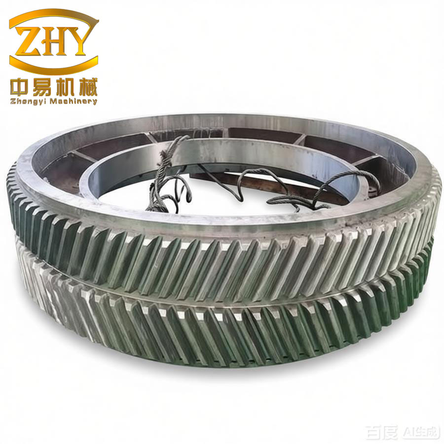
The image above shows a typical herringbone gear pair with the characteristic central gap. The tooth surfaces are often hardened and ground with specific modifications to achieve the desired contact pattern.
5. Conclusions
In this work, I have presented a comprehensive approach for designing profile and lead modifications of herringbone gears using KISSsoft software. The methodology replaces the traditional trial-and-error process with a fast, analytical optimization loop. The key findings from the case study are:
- The optimized modification parameters (profile relief of 15 μm on both pinion and gear, plus 20 μm crowning and 10 μm taper on the pinion) significantly improve load distribution without reducing safety factors.
- The load distribution factor KHβ decreased by 24.6%, indicating much better load sharing.
- Peak-to-peak transmission error decreased by over 42%, promising lower noise and vibration levels.
- Maximum normal line load was reduced by approximately 32%, reducing the risk of surface fatigue.
- The KISSsoft-based design process is efficient, requiring only a few hours of computation instead of weeks of physical prototyping.
The proposed method is readily applicable to various herringbone gear applications, especially in high-speed, high-power transmissions where minimizing vibration and maximizing reliability are critical. Future work could extend the optimization to include multi-objective algorithms that simultaneously consider manufacturing tolerances and cost.
In summary, the use of KISSsoft for herringbone gear modification design proves to be a powerful tool that yields superior performance compared to traditional empirical methods. The resulting gear pair exhibits lower transmission error, more uniform load distribution, and higher reliability, all essential attributes for modern gear drives.