For the design of point milling cutter, this section takes the more common finger cemented carbide end milling cutter as an example for parameter design. The key parameters are blade diameter D and total length L. The design basis of blade diameter D is the tooth groove width at the tooth root of the small end of the spiral bevel gear to be machined. The calculation method of the tooth width at the tooth root of the small end of the spiral bevel gear is used to calculate the tooth width at the tooth root of the small end of the spiral bevel gear to be processed in this section.
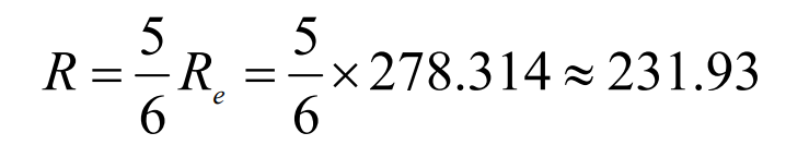
Radius r of arc generating line of spiral bevel gear tooth surface:
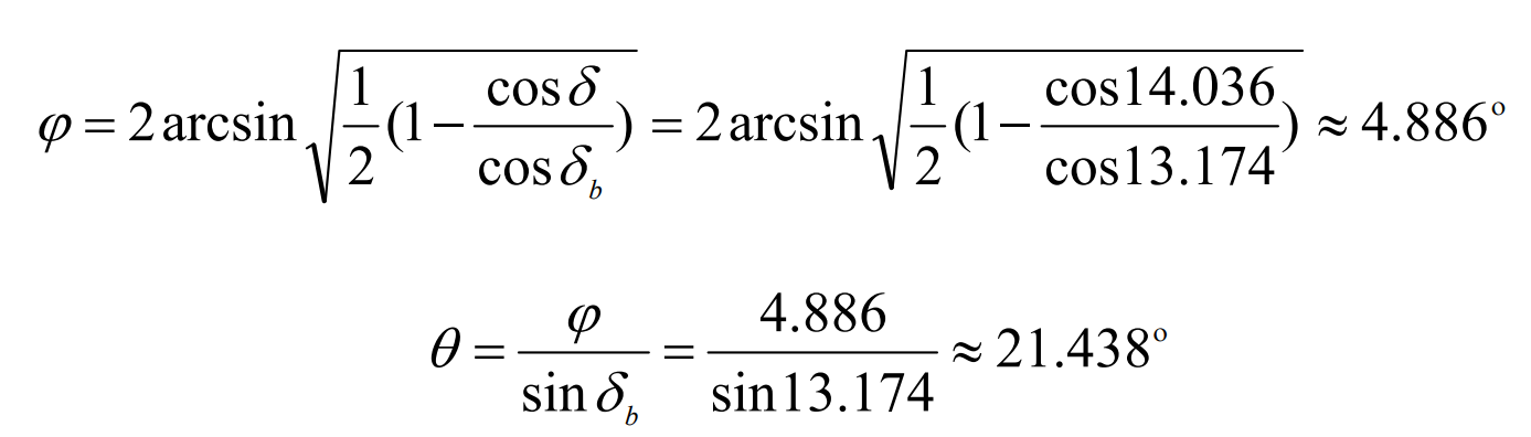
Two key angle values of the generating line of spiral bevel gear tooth surface when rolling from base cone to pitch cone—— φ And θ The calculated values are:
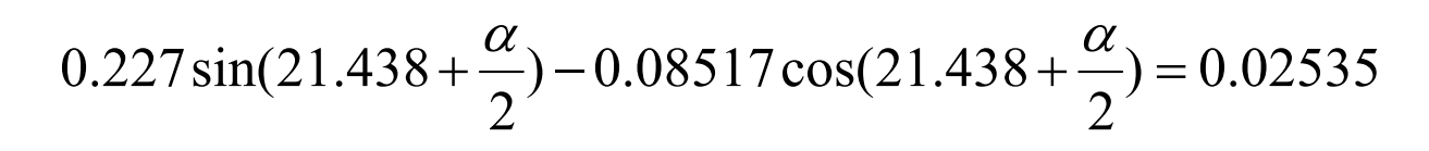
The calculated φ And θ The angle between the tooth groove width at the base cone of the small end of the spiral bevel gear to be machined and the rotation axis can be obtained by substituting the value into the formula and simplifying it—— α Expression for:
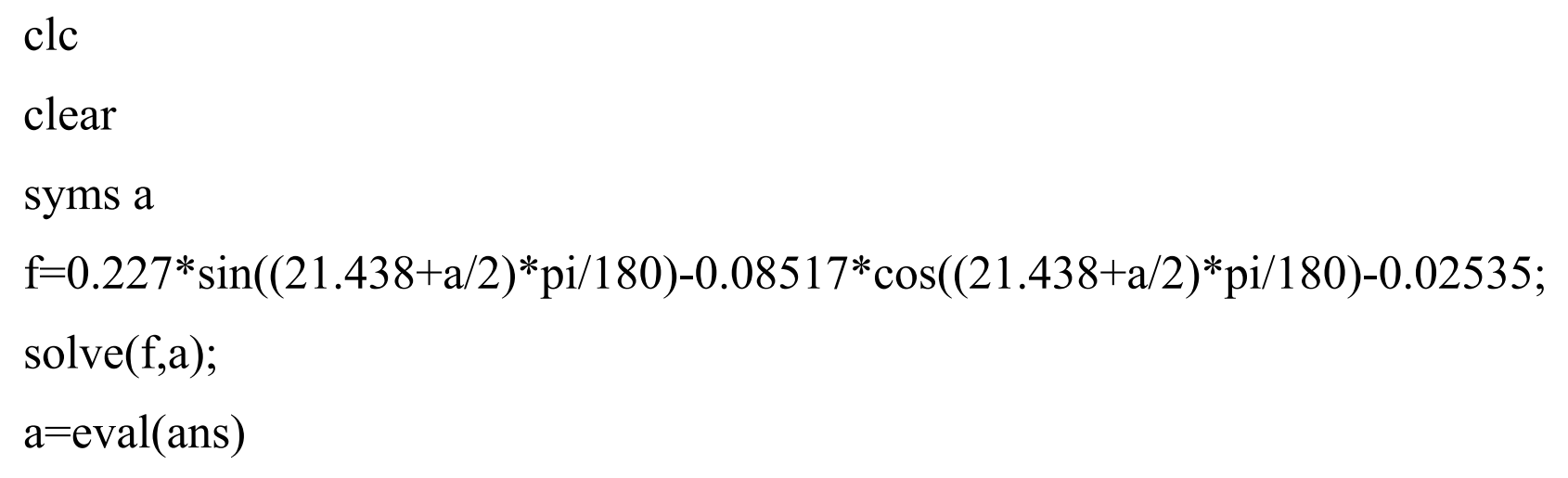
For the formula α The value can be solved with the help of solve and eval functions in MATLAB. The specific solving functions are as follows:
It can be obtained by solving the above function α The value is:
Since the base cone angle and root cone angle of the spiral bevel gear to be machined are equal, the base cone coincides with the root cone, and the tooth groove width at the root cone at the small end of the spiral bevel gear is equal to the tooth groove width at the base cone. For the solution of the tooth slot width at the base cone, the φ= 0 θ= 0 and formula α The numerical value is substituted into the formula for solution.

Then the blade diameter of the finger milling cutter must be less than the tooth groove width s at the small end root cone of the spiral bevel gear. The diameter of the common finger milling cutter that meets this requirement and is closest to the s value is the diameter Φ 6 finger milling cutter.
According to the geometric parameters of the gear blank, the tooth full height of the big end of the spiral bevel gear to be machined can be calculated:

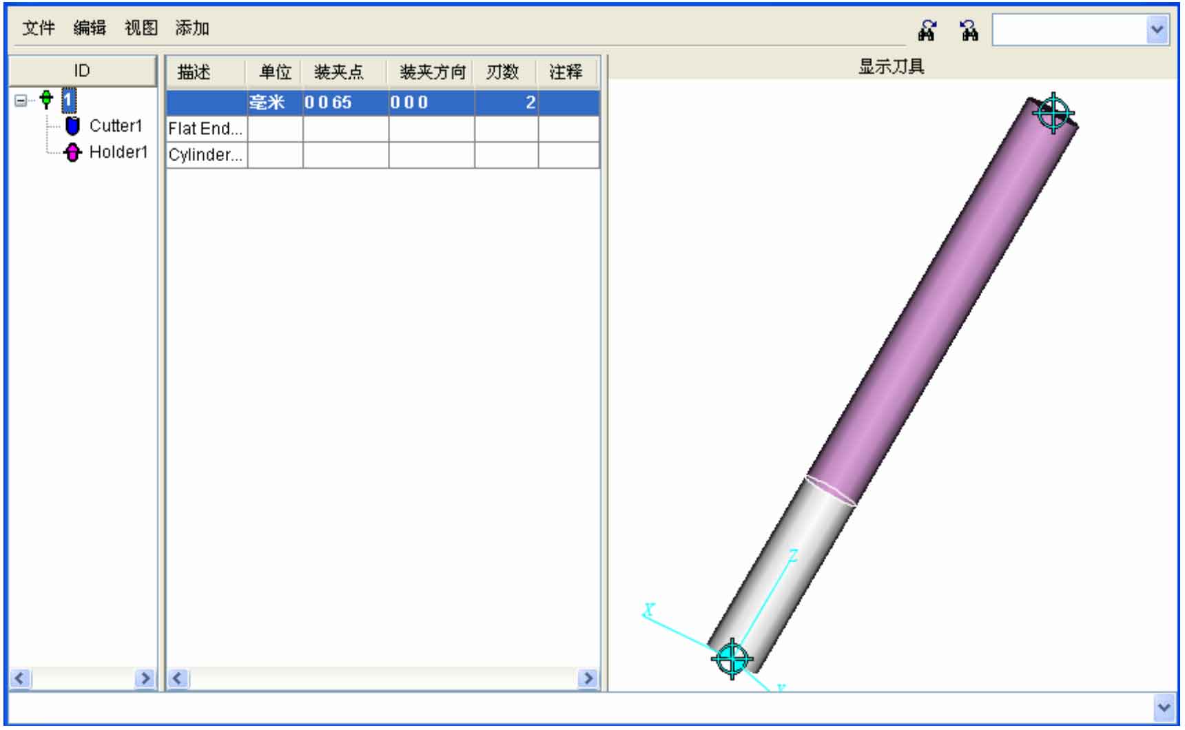
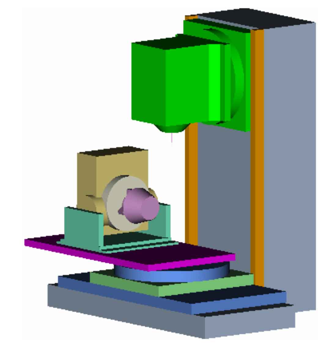
Referring to the existing specifications of cemented carbide finger milling cutter in the market, the commonly used model with a total length of 55 and a blade length of 15 is Φ 6 * 15 * 50 * 2F * 55 ° finger milling cutter can meet the basic requirements of point milling for spiral bevel gear with processing modulus of 9 and number of teeth of 15. According to the geometric dimension of the tool, create a new finger milling cutter in VERICUT’s tool magazine. Because VERICUT’s simulation machining process is a Boolean subtraction operation process, the blade part of the finger milling cutter should be established into a simple cylindrical shape, so that the simulation machining results can be consistent with the actual machining. The built tool is shown in Figure 1. Select the center point of the upper end face of the tool handle of the established tool model – (0 065) as its clamping point and install it on the gear cutting machine model, as shown in Figure 2.