
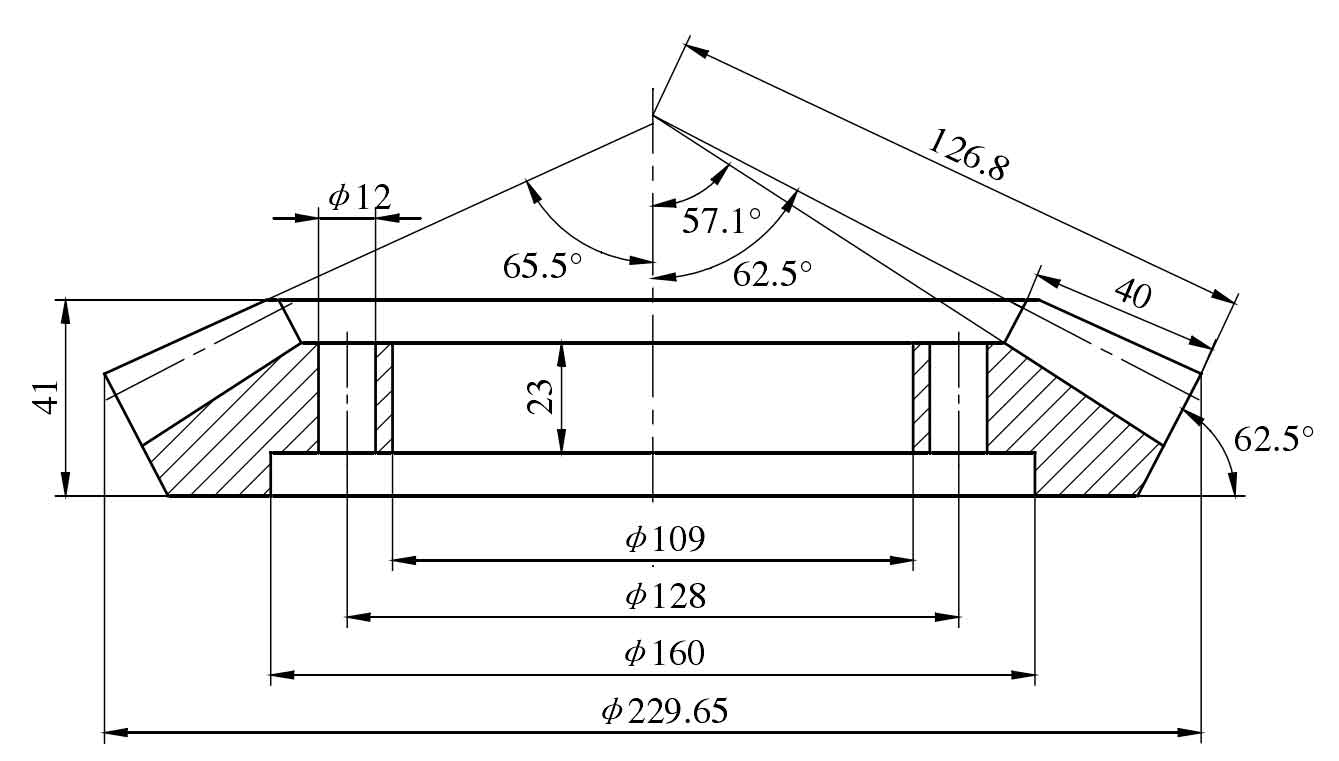
According to the deformation of metal, the precision die forging of spiral bevel gear can be divided into open die forging and closed die forging. Figures 1 and 2 respectively show the part drawing and three-dimensional modeling drawing of driven spiral bevel gear of Chinese automobile. The parameters of spiral bevel gear are shown in the table.

It can be seen from figures 1 and 2 that the shape of spiral bevel gear is relatively special, so it is difficult to adopt the die structure used in the usual closed die forging. For a long time, the research on the precision forging of this kind of spiral bevel gear is only limited to open die forging. Because the forging produced by open die forging will inevitably have flash and skin, which increases the cross-sectional area of the forging and increases the forging forming force required for processing, which will not only increase the subsequent processing, waste energy, and even damage the forging die due to excessive stress. Therefore, it is necessary to find a new closed die forging method to form spiral bevel gear. Based on the brief description of the open die forging die structure of spiral bevel gear and its problems in actual production, the new process of precision forging of spiral bevel gear is analyzed, and the new die structure is discussed.
| Serial number | Name | Code | Company | Calculation formula and description | Parameter value |
| 1 | Number of teeth | Z | Known | 25 | |
| 2 | Large end modulus of tooth profile | m | mm | Known | 9 |
| 3 | Tooth profile angle | α | (°) | Known | 20 |
| 4 | Addendum height coefficient | h*α | Select by table | 0.85 | |
| 5 | Top clearance coefficient | c* | Select by table | 0.188 | |
| 6 | High displacement coefficient | x | x=-0.39(1-1/u*u) | -0.29 | |
| 7 | Tangential displacement coefficient | xτ | Select by table | 0 | |
| 8 | Helix angle at the midpoint of tooth profile | β | (°) | Known | 35 |
| 9 | Spiral direction | Dextral | |||
| 10 | Split cone angle | δ | (°) | Select by table | 62.5 |
| 11 | Graduation circle diameter | d | mm | d = mz | 225 |
| 12 | Cone distance | R | mm | R = d/2sinδ | 126.801 |
| 13 | Tooth width coefficient | φR | φR = 1/3.5-1/3 | 0.315 | |
| 14 | Tooth width | b | mm | Take b= φR and b = 10m the smaller | 40 |
| 15 | Addendum height | ha | mm | ha = (h*a+x)m | 5.04 |
| 16 | Full tooth height | h | mm | h = (2h*a+c*)m | 16.992 |
| 17 | Root height | hf | mm | hf = h-ha | 11.952 |
| 18 | Addendum circle diameter | da | mm | da = d+2hacosδ | 229.6504 |
| 19 | Root angle | θf | (°) | tanθf = hf/R | 5.385 |
| 20 | Tooth apex angle | θa | (°) | θa2 = θf1 | 3.039 |
| 21 | Top cone angle | δa | (°) | δa = δ + θa | 65.5 |
| 22 | Root cone angle | δf | (°) | Δf = δ – θf | 57.1 |
| 23 | Cutter head diameter | D0 | mm | Known | 228.6 |