
1. Hob tooth profile curve
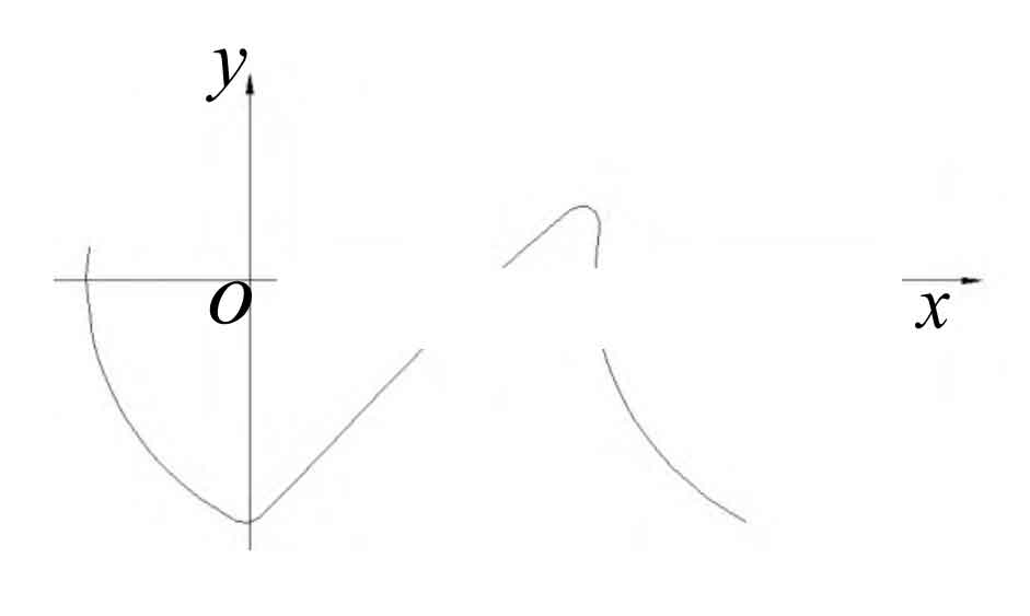
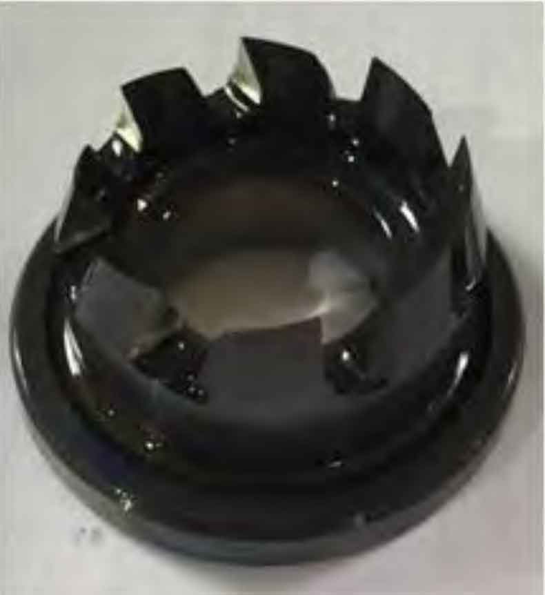
Referring to the design and calculation of the tooth profile of the spiral bevel gear hob for special-shaped instruments by Zhang Xiang and others, the tooth profile curve of the tooth cutter for machining the spiral bevel gear is obtained through calculation, as shown in Figure 1, and the hob is shown in Figure 2.
2. Improvement of machine tool rigidity
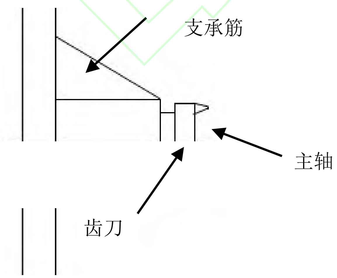
The spiral bevel gear wheel adopts cutting machining, which can increase the axial force of the main shaft and the axial force of the Z axis. Therefore, it is required that the main shaft system of the machine tool should increase a certain degree of stiffness. However, the outward extension of the spindle box of an actual machine tool may lead to insufficient stiffness. In order to solve the insufficient stiffness of the machine tool, it can be obtained through finite element analysis that there should be support ribs, and the ideal method is to adopt a double wall structure. Beautiful, rigid and strong. However, due to the specification requirements of general gear milling machines, the main shaft extension bearing ribs cannot be placed below, as shown in Figure 3.
The main shaft bearing should not be solved with enlarged specifications. Through calculation, a combination of tapered roller bearings or deep groove centripetal thrust ball bearings can be used to enhance axial bearing capacity. The Z-axis ball screw can also be combined with tapered roller bearings or deep groove centripetal thrust ball bearings. Another key point is to control the clearance of the workpiece spindle worm gear pair. By testing the above measures, the machine tool can well adapt to the requirements of semi hobbing processing. At the same time, attention should be paid to the installation of wheels, fixture design, and the spiral bevel gear wheel blank should have a certain bearing area, which cannot be too small.